Page 12
3.2.4 UnderwaterLightingGFCIWiring
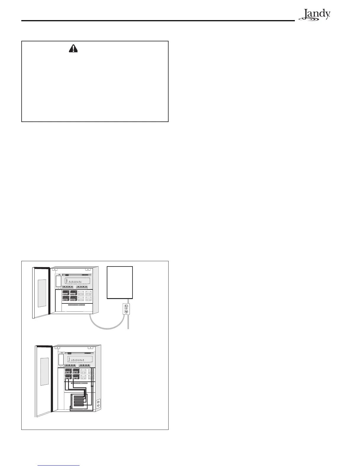
Figure 4. GFCI Installation for Underwater
Lighting
GFCI
Outlet
Standard Power Center
GFCI Outlet
(Optional)
Sub-Panel Power Center
3.2.5 JandyPoolandSpaLightsWiring
The JandyPoolandSpaLights can be wired into
the Jandy AquaLink RS control system to ensure
simplified operation of the lights, as well as a
means to synchronize the color change function.
Connect the lights to one of the auxiliary relays in
the Power Center.
NOTE It is recommended to connect one light per
relay so each light can be controlled separately.
However, up to four lights can be connected on
a single relay. If there are more than four lights
installed on one AquaLink RS system, ensure
there is more than one auxiliary relay available
in the Power Center.
Refer to Figures 5 and 6 to connect the Jandy Pool
and Spa Lights to the Power Center.
NOTE The Jandy Pool and Spa Lights are available
in 120-volt and 12-volt versions. If installing a
12-volt light, a 120-volt/12-volt step-down (AC)
transformer must be used. For more information
about 12-volt installations, refer to the Jandy
Digital,Color Changing,Underwater Pool and
Spa Lights Installation and Operation Manual.
CAUTION
A Ground Fault Circuit Interrupter (GFCI) must be
provided in high voltage pool/spa lights. Do not
use a GFCI circuit breaker.The conductors on
the load side of the GFCI circuit shall not occupy
conduit, boxes, or enclosures containing other
conductors unless the other conductors are also
on the load side of a GFCI. Refer to local codes
for complete details.
1. For a Standard Power Center, install a GFCI
receptacle next to the breaker panel. For
a Sub-Panel Power Center install a GFCI
receptacle in the Power Center (use the
knockout provided on the right side of the
Sub-Panel Power Center). See Figure 4.
2. Connect neutral and hot wire (from circuit
breaker) to the LINE side of the GFCI.
3. Connect neutral (white wire) and the hot
(black wire) from the light to the LOAD
side of the GFCI.
4. Connect ground from the light to the
grounding bar inside the Power Center.

 Loading...