Page 16
3.4.3 GuidelinesforHaywardHeaters
1. Remove heater service door.
2. Remove factory-installed wire nut between
two (2) red wires labeled "CONNECTION
FOR FIELD INSTALLED CONTROL
SWITCH" (see Figure 11).
3. Wire nut two (2) heater wires from
AquaLink RS P.C. Board to the two (2) red
wires of the heater (see Figure 12).
4. Set the thermostat selector switch to
ON, HIGH, or SPA, and set the heater
thermostat(s) to maximum.
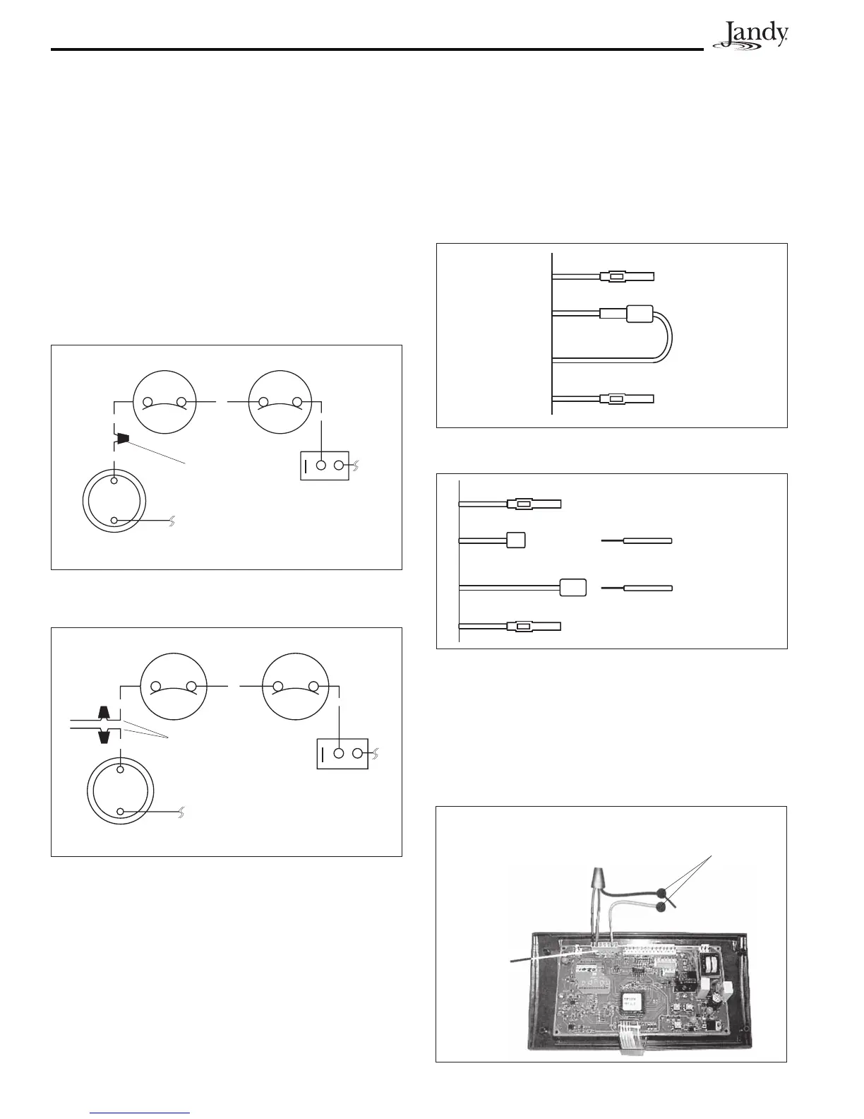
3.4.4 GuidelinesforPentairHeaters
1. Remove the heater service door.
2. Separate the black wires (common) from
each other (see Figure 13).
3. Connect the wires from the Power Center
PCB to the two black wires on the heater
(see Figure 14).
3.4.5 GuidelinesforRaypakHeaters
For the 2-wire/1 function configuration, connect
the orange/black and black/orange wires to one
contact and the yellow/black wire to the other
contact (see Figure 15).
Limit Switch
Factory
Installed
Wire Nut
R
Limit Switch
R
V
OFF ON
BL
Pressure Switch
Figure 11. Hayward Heater Wiring Before
Modification
ON
BL
Limit Switch Limit Switch
R
R
V
OFF
Pressure Switch
Wires to
Power Center
PCB
Figure 12. Hayward Heater Wiring with
AquaLink RS
Figure 13. Pentair Heater Wiring Before
Modification
VIO
BLK
BLK
RED
Figure 14. Pentair Heater Wiring with AquaLink RS
Wires from
Power Center
PCB
VIO
BLK
BLK
RED
Figure 15. Raypak Heater Wiring with AquaLink RS
P7
Terminal
To
AquaLink
RS System
4. Turn the heater toggle switch on, and the
heater thermostat(s) to max.
5. When connecting an AquaLink RS Control
to a Pentair Heater, Pentair requires that
you install the low voltage thermostat wires
in conduit separate from ANY line voltage
wires.

 Loading...