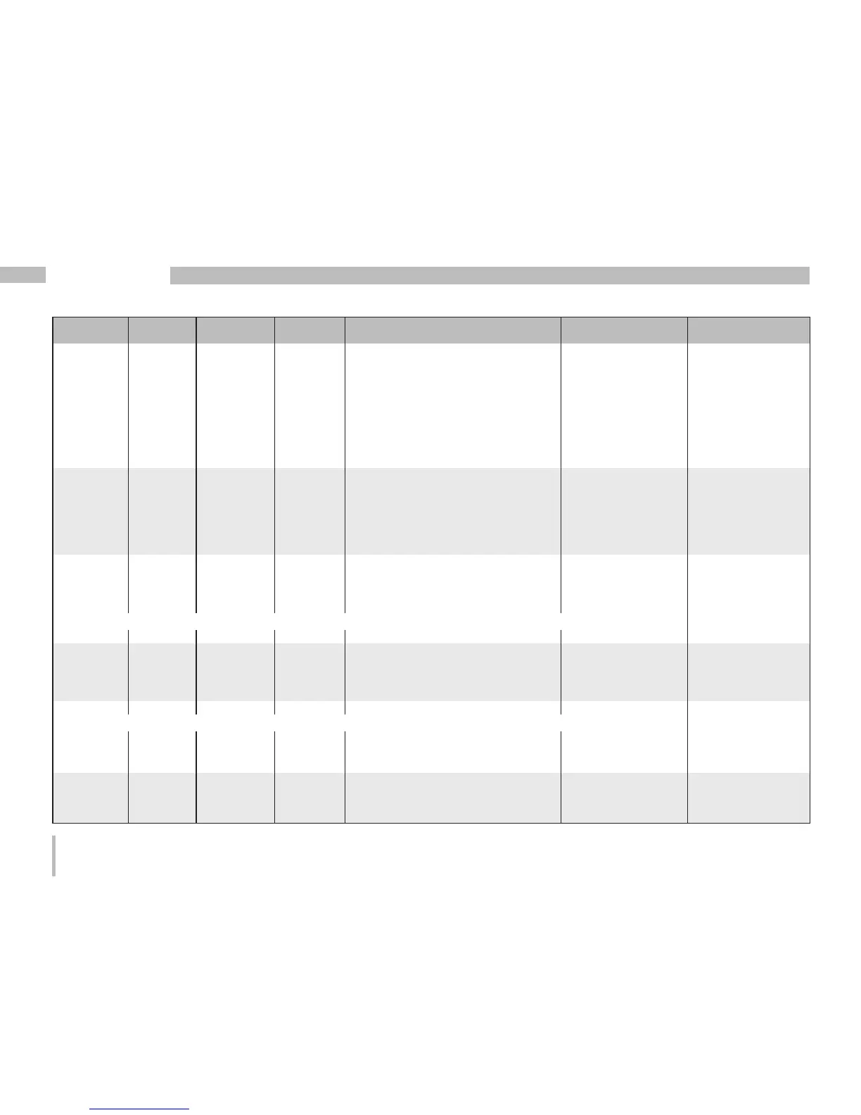
Adress Format RD/WR Unit Note Adjustment Range Default
81 SHORT RD/WR - Secondary address, 0..99
extended section 1
82 SHORT RD/WR - Secondary address, 0..99
extended section 2
83 SHORT RD/WR - Secondary address, 0..99
extended section 3
84 SHORT RD/WR - Secondary address, 0..99
extended section 4
500 SHORT RD/WR - Terminal assignment, I L1 -3..0..+3
1)
+1
501 SHORT RD/WR - Terminal assignment, I L2 -3..0..+3
1)
+2
502 SHORT RD/WR - Terminal assignment, I L3 -3..0..+3
1)
+3
503 SHORT RD/WR - Terminal assignment, U L1 0..3
1)
1
504 SHORT RD/WR - Terminal assignment, U L2 0..3
1)
2
505 SHORT RD/WR - Terminal assignment, U L3 0..3
1)
3
506 SHORT RD/WR - Clear min. and max. values 0..1 0
507 SHORT RD/WR - Clear energy meter 0..1 0
508 SHORT RD/WR - Force write EEPROM 0..1 0
Note: Energy values and minimum and maximum values are written to the EEPROM every 5 minutes.
509 SHORT RD/WR - Voltage connection diagram 0..8
2)
0
510 SHORT RD/WR - Current connection diagram 0..8 0
511 SHORT RD/WR - Relative voltage for
THD and FFT 0, 1 0
The voltages for THD and FFT can be shown on the display as L-N or L-L values. 0=LN, 1=LL
600 UINT RD/WR - Metering range exceedance 0..0xFFFFFFFF
746 SHORT RD/WR s Period of time after which the
backlight will switch to standby 60 .. 9999 900
747 SHORT RD/WR s Brightness of the standby backlight 0 .. 9 0
1)
0 = No measurement of the current or voltage path.
2)
The setting 8 is equal setting 0.

 Loading...