88
UMG 96RM
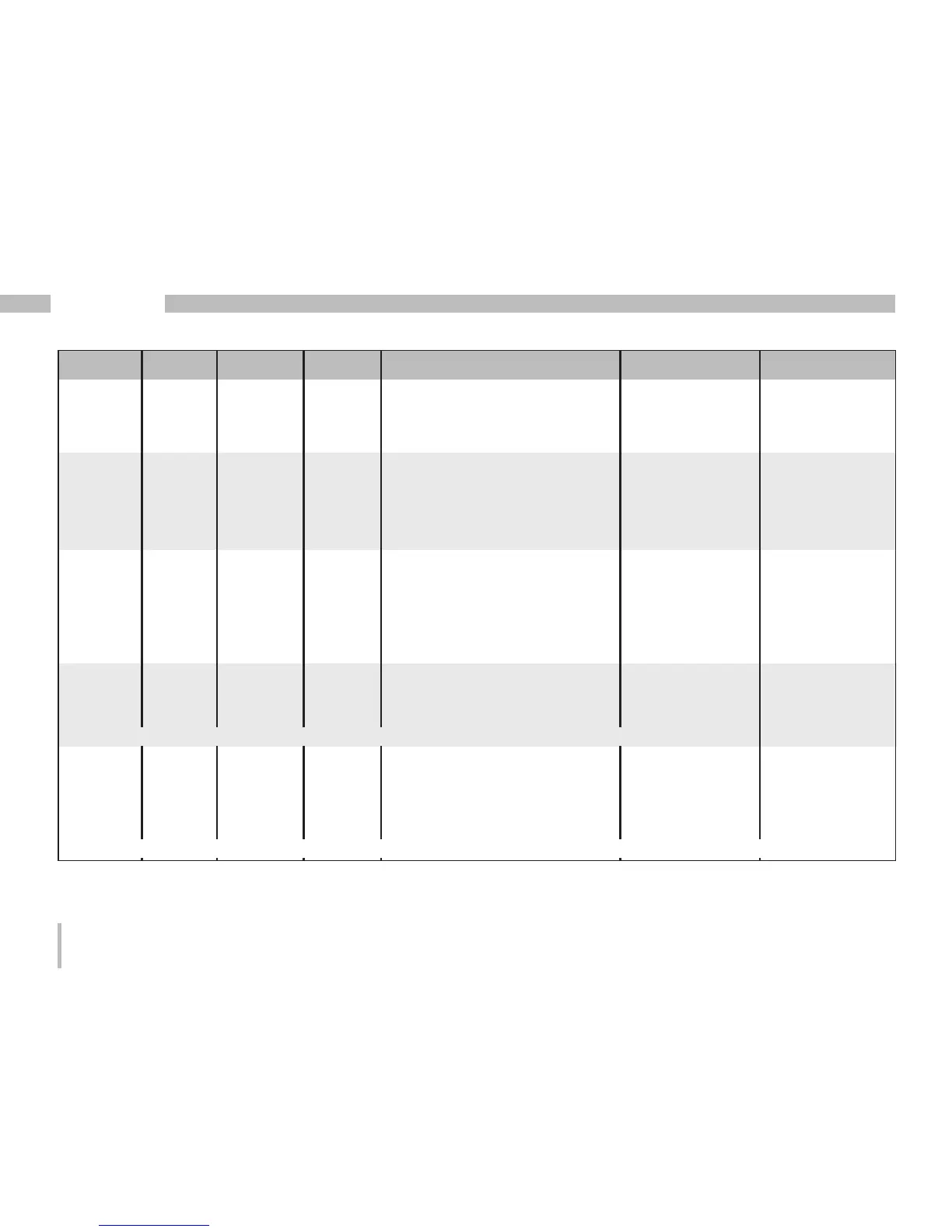
Address Format RD/WR Unit Note Adjustment Range Default
143 SHORT RD/WR s Comparator 2C, lead time 0..32000 0
144 SHORT RD/WR - Comparator 2C, Operator 0,1 0
“>=” = 0 “<” = 1
200 SHORT RD/WR - Select the source for
Digital output 1 0..4
*1
0
201 SHORT RD/WR - Digital output 1 inverter 0..1
*2
0
202 SHORT RD/WR - Select the source for
Digital output 2 0..4
*1
0
203 SHORT RD/WR - Digital output 2 inverter 0..1
*2
0
500 SHORT RD/WR - Terminal assignment, I L1 -3..0..+3 +1
501 SHORT RD/WR - Terminal assignment, I L2 -3..0..+3 +2
502 SHORT RD/WR - Terminal assignment, I L3 -3..0..+3 +3
503 SHORT RD/WR - Terminal assignment, U L1 0..3 1
504 SHORT RD/WR - Terminal assignment, U L2 0..3 2
505 SHORT RD/WR - Terminal assignment, U L3 0..3 3
506 SHORT RD/WR - Clear min. and max. values 0..1 0
507 SHORT RD/WR - Clear energy meter 0..1 0
508 SHORT RD/WR - Force write EEPROM. 0..1 0
Note: Energy values and minimum and maximum values are written to the EEPROM every 5 minutes.
509 SHORT RD/WR - Voltage connection diagram 0..7 0
510 SHORT RD/WR - Current connection diagram 0..8 0
511 SHORT RD/WR - Relative voltage for
THD and FFT 0, 1 0
The voltages for THD and FFT can be shown on the display as L-N or L-L values. 0=LN, 1=LL
*1
0 =comparator group, 1=pulse output, 2=value from an external source (Modbus), 3=reserved, 4=reserved
*2
0=not inverted, 1=inverted

 Loading...


