14
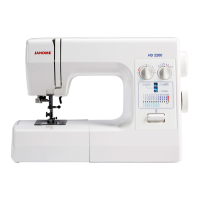
F1 Fuse
(AC250V 3.15A)
F2 Fuse
(AC250V 3.15A)
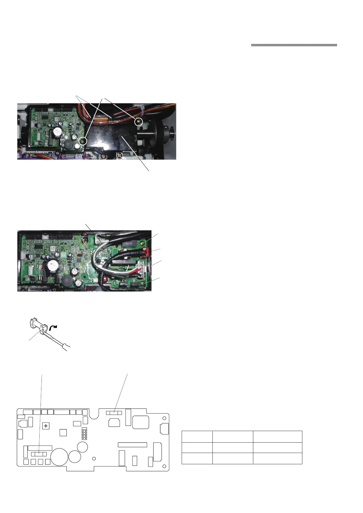
4. Circuit Board-A
To remove:
Remove the top cover.
Pull out connectors from the printed circuit board A.
Remove the cords from the cord clips
q
.
Remove the setscrews
w
and the printed circuit board
A case
e
.
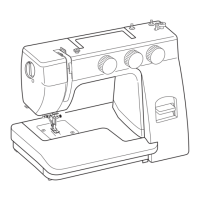
Pull out the connectors under the case lid.
Remove setscrews
r
and printed circuit board A.
To attach:
Install the printed circuit board A and secure it with the
setscrews
r
.
Insert the following connectors:
t
Machine socket (primary)
y
Power transformer (primary)
u
Driving motor
Attach the printed circuit board A case
e
and
secure it with the setscrews
w
.
Insert the remaining connectors and secure the cords
with the cord clips
q
on the case lid.
Attach the top cover.
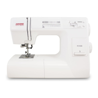
NOTE:
Do not disconnect the connectors by pulling on cord.
To disconnect, grasp the connector, not the cord.
z
x
c
v
b
n
m
,
q
w
e
t
r
y
u
r
Changing the Fuse
Remove the Fuse from Fuse clip
q
with a screw
driver.
Insert a new fuse and push it down into the fuse clip.
NOTE:
Replace the fuse with the same type and rating.
If there is any trace of burning, browning or other
abnormalities on the printed circuit board A, replace it.
z
x
q
Fuse Manufacture Type
F1 SOC ET-3.15A-250V
F2 SOC ET-3.15A-250V