P/N 960-000180R_Rev. 1 {EDP #233427} © 2016, JAPAN CASH MACHINE CO., LTD.
Section 4 DBV® Series DBV-400 Banknote Validator Disassembly/Reassembly
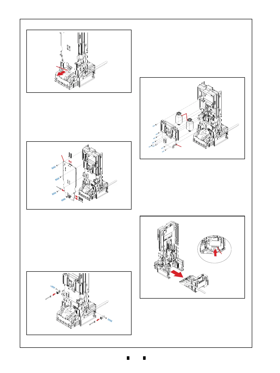
5. Unplug the single (1) Connector (Figure 4-5 a).
6. Remove the four (4) Mounting Screws (Figure 4-
6 b
1
through b
4
) securing the CPU Circuit Board
(Figure 4-6 a) to the Main Frame Assy. (Figure 4-
6 d).
7. Unplug the five (5) Connectors (Figure 4-6 c
1
through c
5
), and remove the CPU Circuit Board
from Main Frame Assy. (Figure 4-6 d).
Side Sensor Removal
To remove the Side Sensors, proceed as follows:
1. Unplug the two (2) Connectors (Figure 4-7 c
1
and c
2
).
2. Remove the two (2) Mounting Screws (Figure 4-7
b
1
and b
2
) securing the Side Sensors (Figure 4-7
a
1
and a
2
), and remove the two (2) Side Sensors
from the Main Frame Assy. (Figure 4-7 d).
Motor Harness Assy. Removal
To remove the Motor Harness Assy., proceed as
follows:
1. Remove the eight (8) Mounting Screws (Figure 4-
8 b
1
and b
8
) securing the Motor Gear Cover D4
(Figure 4-8 a), and remove the Motor Gear Cover
D4 from the Main Frame Assy. (Figure 4-8 c).
2. Remove the Motor Harness Assy. (Figure 4-8 d)
from the Main Frame Assy.
Inside Validation Sensor Board
Removal
To remove the Inside Validation Sensor Board, pro-
ceed as follows:
1. Press the Validation Guide Open/Close Latch
(Figure 4-9 a) upward and pull the Validation
Guide (Figure 4-9 b) out of the Main Frame.
2. Remove the four (4) Mounting Screws (Figure 4-
10 b
1
through b
4
) securing the Validation Guide
Cover Assy. (Figure 4-10 a), and separate the
Validation Guide Cover Assy. from the Main
Frame (Figure 4-10 c).
Figure 4-5 Unplugging Connector
Figure 4-5 Unplugging Connector
Figure 4-6 CPU Circuit Board Removal
Figure 4-6 CPU Circuit Board Removal
Figure 4-7 Side Sensor Removal
Figure 4-7 Side Sensor Removal
Figure 4-8 Motor Harness Assy. Removal
Figure 4-8 Motor Harness Assy. Removal
Figure 4-9 Validation Guide Removal
Figure 4-9 Validation Guide Removal