P/N 960-000180R_Rev. 1 {EDP #233427} © 2016, JAPAN CASH MACHINE CO., LTD.
Section 4 DBV® Series DBV-400 Banknote Validator Disassembly/Reassembly
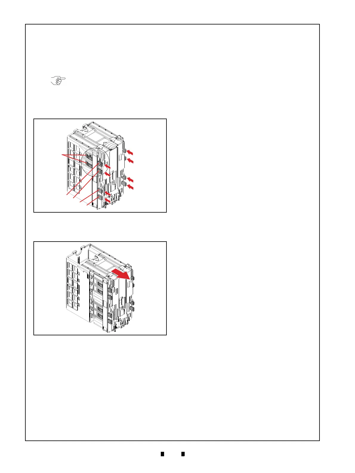
Box Base Assy. Removal
To remove the Box Base Assy., proceed as follows:
1. Insert the Cash Box Disassembling Tool (8
pieces) into the indicated eight (8) spots (Figure
4-14 a
1
through a
8
) to unlock the tabs on the Box
Base Assembly (Figure 4-14 b).
2. Remove the Box Base Assy. (Figure 4-15 a) from
the Box Frame D-4 (Figure 4-15 b).
NOTE: To unlock each tab, make sure
the square-cut beveled surface of the
Cash Box Disassembling Tool (refer to
Figure 4-14 c) faces outward, with the
flat surface facing the side of the Box
Base Assembly.
Figure 4-14 Box Base Assy. Removal 1
Figure 4-14 Box Base Assy. Removal 1
Figure 4-15 Box Base Assy. Removal 2
Figure 4-15 Box Base Assy. Removal 2