radio control system
EN
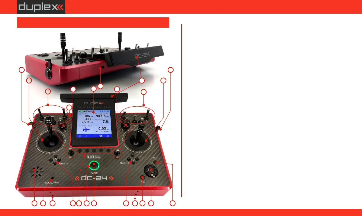
2.2.1 Control Identification DC-24II
1. Right Stick 1, 2 – the DC-24II Transmitter Supports Modes 1-4, see
Control Sticks -> mode change.
2. Left Stick 3, 4 – the DC-24II Transmitter Supports Modes 1-4, see
Control Sticks -> mode change
3. Swappable and Assignable Switches: Sa, Sb, Sc, Sd, Se, Sf, Sg, Sh, Si, Sj
4. Digital Trims for the Left Stick T3, T4
5. Digital Trims for the Right Stick T1, T2
6. Right Side Control Lever "5"
7. Left Side Control Lever "6"
8. Rotary Control Knob "7"
9. Rotary Control Knob "8"
10. LCD Display
11. Function Buttons "F1 – F5"
12. Transmitter On/Off "Power Switch”
13. "3D” Control Selector
14. "Menu” Button
15. "ESC” Button
16. Antenna/ Transmitter Handle
17. USB-C connector (Charging/connecting to PC)
18. Headphone connector / PPM connector
19. LED Indicators
20. Speaker
21. Harness Bracket (optional accessory) Installation Holes
22. Microphone
2.2 Description of the transmitter - DC-24II
3
1
2
3
4
5
67
8
9
11
12
13
15
14
16
17
1820
19
2121
10
22
15
www.modellmarkt24.ch



 To Next Page