radio control system
EN
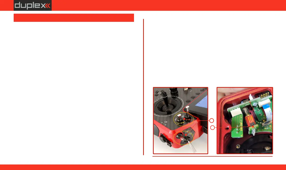
6.2.1 Switch disassembly and assembly procedure
1. Switch off the transmitter and remove the radio back cover.
Be sure to disconnect the transmitter battery pack
connector.
2. With the specialized wrench (not included) carefully loosen and
remove the switch installation nut.
3. Carefully hold the switch by its printed circuit board assembly
and slowly pull it out. Use this method to also remove and
exchange all of the other switches. After re-assembling and
turning on your transmitter the software will sound a warning
reminding you that you have executed a change. Always
reinspect all assigned functions of the switches before
attempting to fly.
6.2 Replaceable switches
3
2
One of the most important features of a JETI transmitter is the switch
function assignment flexibility.
The DS-24 II transmitter automatically detects the type of switch and
assigns the selected function. There are many switches available to
suit different needs. See your JETI retailer for switch availability.
You may either swap the existing switches around or take advantage
of the optional accessories and create your own custom
configuration.
Factory Switch Configurations for the DS-24 II Transmitter
Sa - 3 position short switch
Sb - 2 position long switch
Sc - 2 position short switch
Sd - 2 position long switch
Se - 3 position long switch
Sf - 2 position short switch
Sg - 2 position spring-loaded long switch
Sh - 2 position short switch
Sm - 2 position switch (non-replaceable - back cover)
Sn - 2 position switch (non-replaceable - back cover)
Sm - 2 position switch (non-replaceable 2xbutton - back cover)
Sn - 2 position switch (non-replaceable 2xbutton - back cover)
69
www.modellmarkt24.ch



 To Next Page