radio control system
EN
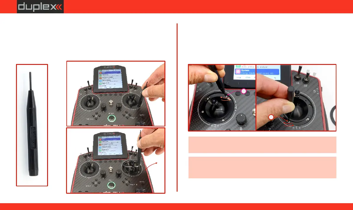
6.1.5 Setting the Range of the gimbal
At the transmitter, it is possible to define the range of motion for the
gimbal.
2. Setting the Upper Motion Limit of the Throttle stick:
Insert the "allen key" into screw
"E”.
Turning the screw counterclockwise increases the range of
motion (see Fig. 6.22).
Turning the screw clockwise decreases the range of motion (see
Fig. 6.22).
E
E
-
+
-
+
Fig. 6.22Fig. 6.22Fig. 6.22
Left
Right
Fig.Fig. 6.20Fig. 6.20
Fig. 6.21Fig. 6.21Fig. 6.21
(a)
(b)
Fig.Fig. 6.19Fig. 6.19
(c)
Note: When fully loosened, the head of the screw must not be (a)
higher than the seating surface of the cover ring (Fig. 6.15).(b)
Note: It is recommended to determine the desired position of the
stop (end of travel) by gradually moving in the adjusted axis
(during the adjustment).
(a)
1. (a)(b)
Place the magnetic key on the cover ring of the gimbal and
remove it from position .
(c)
59
www.modellmarkt24.ch