radio control system
EN
Note: When fully loosened, the head of the screw must not be (a)
higher than the seating surface of the cover ring (Fig. 6.15).(b)
Note: It is recommended to determine the desired locking by
gradually moving in the adjusted axis (during the adjustment).
Caution:
Tighten the screws with care to avoid damaging the gimbal.
F
F
-
+
-
+
LeftRight
Fig. 6.17Fig. 6.17Fig. 6.17
(d)
(e)
Fig. 6.18Fig. 6.18Fig. 6.18
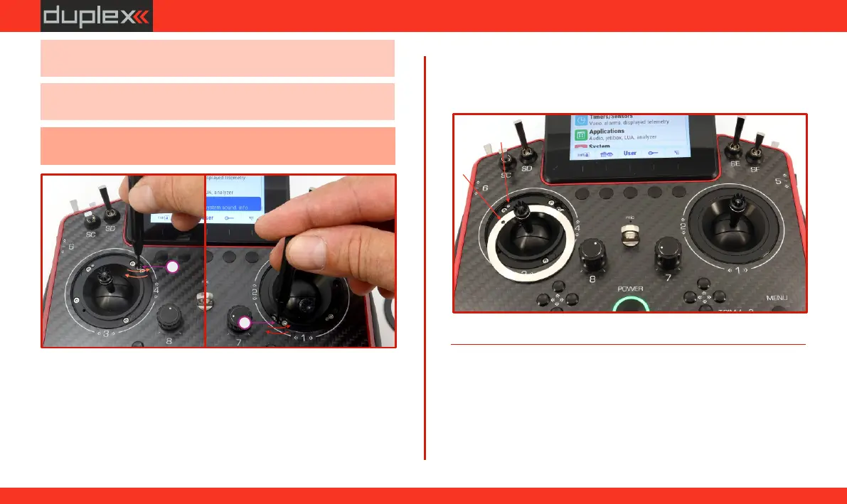
5. (e) Place the cover ring back onto the gimbal so that its groove
fits precisely over the locking pin (in the area of adjustment
(d)
screw ") on the gimbal. Visually, the ring should lie in line "D”
with the front side of the transmitter. ).
58
www.modellmarkt24.ch