radio control system
EN
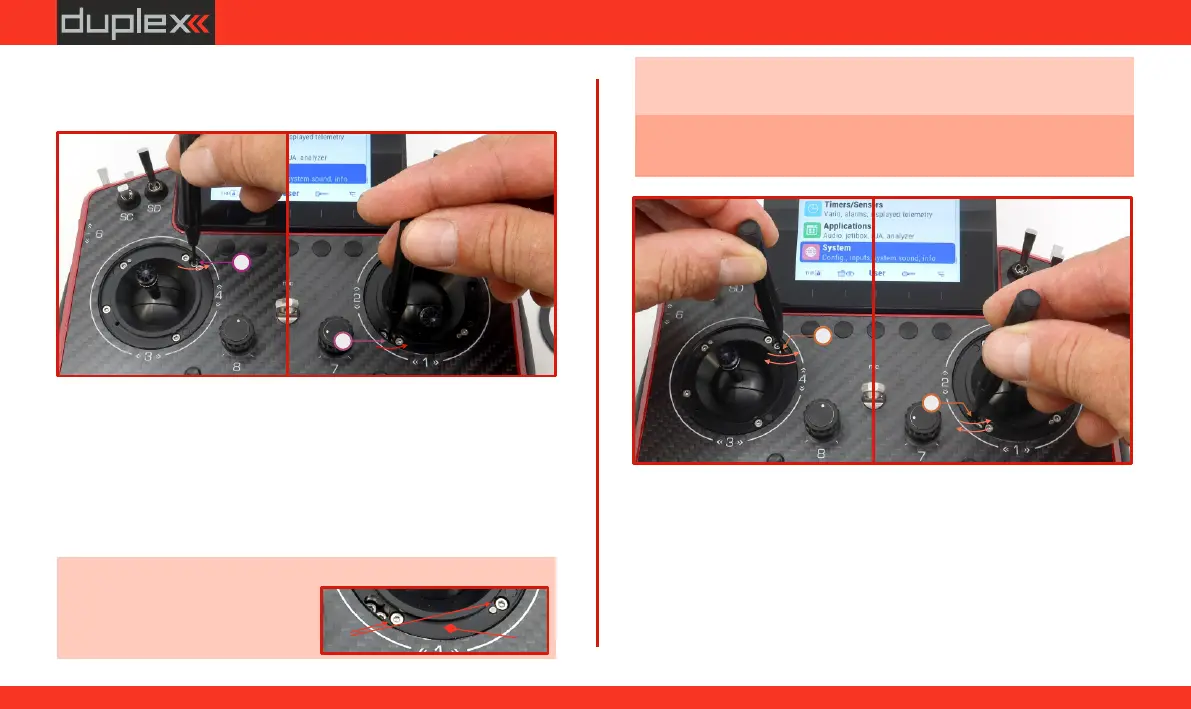
2. Insert the "allen key" into the adjustable screw and loosen "F”
the locking step by turning it counterclockwise (if it is
activated).
3. Setting Smooth Locking (Brake/Throttle):
Insert the allen key into screw .
"G”
Turning the screw clockwise increases the strength of the
smooth brake. Resulting in greater resistance when moving the
gimbal in this axis (see Fig. 6.16).
Turning the screw counterclockwise decreases the strength of
the smooth brake. Resulting in less resistance when moving the
gimbal in this axis (see Fig. 6.16).
Note: When fully loosened, the head of the screw must not be
(a)
higher than the seating surface
of the cover ring (Fig. 6.15).(b)
F
F
-
-
G
G
-
+
-
+
Fig. 6.14Fig. 6.14Fig. 6.14
Fig. 6.16Fig. 6.16Fig. 6.16
(b)(b)(b)
(a) (a) (a)
Obr. 6.15Obr. 6.15Obr. 6.15
Note: It is recommended to determine the desired locking by
gradually moving in the adjusted axis (during the adjustment).
Caution: Tighten the screws with care to avoid damaging the
gimbal.
LeftRight
LeftRight
4. Setting the ratchet Locking (Brake/Throttle):
Insert the allen key into screw .
"F”
Turning the screw clockwise increases the force of the ratchet
brake. Resulting in greater resistance when moving the cross
controller in this axis (see Fig. 6.17).
Turning the screw counterclockwise decreases the force of the
ratchet brake. Resulting in less resistance when moving the
cross controller in this axis (see Fig. 6.17).
57
www.modellmarkt24.ch