computer
radio
control
system
EN
4.
4.
defined (completely
off
) throttle position once the assigned
swit
ch
is
activat
ed
.
5.
T
hr
ottle
Idle
S
etting
This
feature is used to set the idle position for your throttle and will
prevent your engine from shutting-off when you moving
throttle
stick to its low position.
T
he
minimum throttle setting is defined
b
y
editing the “Idle Offset”
value
.
When this function has
been
activat
ed
,
the minimum throttle setting
(idle
point)
is
defined by
the
offset value as a
per
c
entage
.
Standard throttle function is
not
affected by the idle offset
setting
.
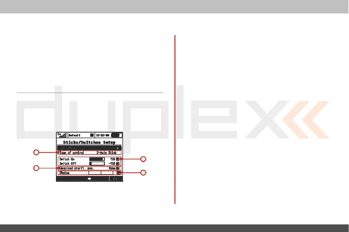
9.3.2 Sticks / Switches
S
etup
This
menu contains System Stick/Switch settings and c
onfiguration.
V
arious
functions can be activated by any Switch, Stick or
K
nob
position. Switch setting enables you to set the points when
y
our
desired
function/timer/telemetry
can be turned
ON
or
OFF
.
1
2. Switch
ON/OFF
P
oin
ts
Any
proportional function can be set as a system switch.
This
menu
item enables you to assign the travel
percentage
at which a
desir
ed
function can be turn
ON
or
OFF
.
“Switch-ON” –
T
he
point when the control element positon will
switch a function ON.
“Switch-OFF”
–
T
he
point when the control element positon will
switch a function
OFF
.
By
default, the system setting
f
or
all
proportional channels and
f
or
all
inputs
is
set to function the same as a 3-position
switch.
a)
A
function above this point
is
considered to be
“S
witch
ON”
b)
A
function in this range (middle) can be considered to be
either
“S
witch
ON”
or
“S
witch
OFF”
c)
A
Function below this point
is
considered to be“Switch
OFF”
If
the switch setting
is
set at same level for “Switch
ON”
and
“S
witch
OFF”
the proportional
channel/func
tion
output
will
be the same as
a
2-position
switch.
3. Required Preflight
P
osition
For
any functions assigned to the
Switch,
K
nob
or
Stick
;
any
pr
eflight
3
1. Switch
&
Stick
T
ype
2
initial
position can be
pr
og
rammed
.
If
the
pre-programed
S
wit
ches
,
K
nobs
or
Sticks
are not in required preflight position while model is
4
being
activat
ed
,
system will refuse to switch to this
model
.
T
he
transmitter screen will display the function that is not in
pr
e
-
pr
og
rammed
,
correct preflight
position.
T
he
first menu line item lists the c
ontr
ol
’
s
number and the
sec
ond
item lists the type of control element. Using the “F2” and “F3”
function
buttons
you can scr
oll
through
channels
,
with the
“F5
(Ok)”
butt
on
you can
exit
the menu scr
een.
4. Function Status
Displa
y
Position and status of the control is displayed in the status
bar
.
On
the right side of this menu you can see status of the switch
func
tion