4.
4.
computer
radio
control
system
EN
9.3.4
L
ogical
S
witches
I
f
you want to have single or multiple transmitter functions which
ar
e
controlled based upon the condition of other control c
onditions
then setting up a
log
ical
switch
is
the way to
go
.
Each
log
ical
switch is
defined by a logical expression.
T
he
logical expression contains
a
logical function and the relationship of the other conditions
which
must exist for the logical function to be
activat
ed
.
T
he
end result is
that your logical switch can either work like a 2-positon
swit
ch
(
ON/OFF)
or
like
a proportional 3-position switch (ON/Center/OFF).
1.
Cr
ea
ting
a
L
ogical
S
witch
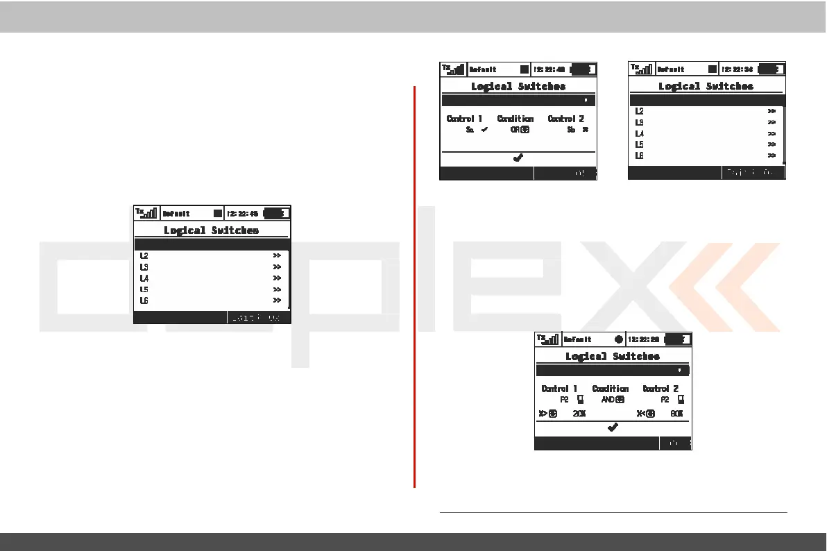
Up to 16
independent
logical switches can be
cr
eated
.
Select one of
the
numbered
lines and press the „3D button“ to access the
log
ic
switch setup
menu
.
To
enable the switch highlight and change
the
enabled value to
“Yes”
.
Once activated you can see the c
ontr
ol
inputs and conditions on the menu screen. First set the c
ontr
ol
inputs #1 and #2 by assigning functions to
swit
ches
,
sticks or
k
nobs
.
After that, select your desired logic
statement
(OR, YES,
Multi).
On
the
bottom
of the screen the result of your logical expression is
displayed by either a check mark or an
„X“
,
depending
upon
the
current conditon
stat
e
.
2.
L
ogical
Switch Proportion
C
alcula
tion
L
og
ical
rules can also be created when your logical switch
uses
proportional
channels
.
To
enable proportional evaluation press
the
„F2(Prop)“
button
when you select your input c
ontr
ols
.
When
y
ou
allow the use of proportional controls an additional condition
menu
will
appear
.
I
n
this menu the conditions can be set by
per
c
entage
value of the channel as well as by the value from which the
swit
ch
will
be
in
its
full
ON/OFF
position.
T
hose
conditions
will
then be
used
to calculate the
log
ical
r
esult.
Example: This
figure shows the use of proportional processing by a
logical
switch. In this
example,
if
the
P2
stick
is
moved between
20%
and
80%
of
its
tr
av
el
the
logical
switch
is
in
the
ON
position.
If
the
P2 stick is
moved from
0%
to
20% or
from
80%
to
100%
then the logical
switch
is
in
the
OFF
position.
All
16
logical
switches
c
an
be
c
onfigured this way
if
needed
.