·14·
A
C
D
S
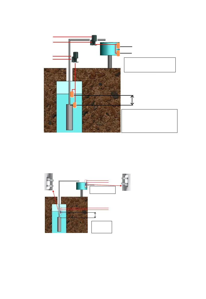
A:the Installation location of
overflow high water level sensor.
B:the Installation location of
overflow low water level sensor.
1. C:the Installation location of pump
dryed high water level sensor.
2. D:Pump outlet,the Installation
location of pump dryed low water
level sensor.
3. S about 1-3 m .
B
To Water level
sensor connector
B1 connect white cable
B2 connect green cable
A2 connect green cable
A1 connect black cable
The installation figure of Sensor A
If you selected water level sensor B, then water sensor installation method is
shown below:
connect green cable
connect black cable
connect green cable
connect white cable
A:the Installation location of
overflow water level
sensor.
1. B:the Installation
location of pump dryed
water level sensor.
2. C:Pump outlet.
3. S about 1-3 m .
A
B
C
S
For dry protection, the end with cable
of sensor should be upwards
For over-
flow protection, the end with cable of
sensor should be downwards.
The installation figure of Sensor B
 Loading...