·71·
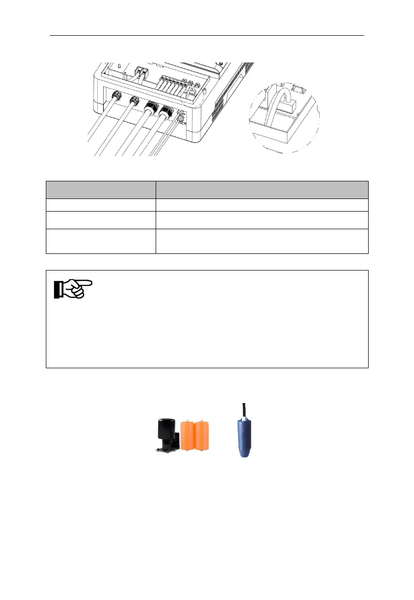
Figure6-5 Water level sensor interface define
Table 6-4
Dry protection and Overflow protection common
pin,
Notice!
Above three input signal of water level sensors is passive signals, which is
matching opening or closing signal of the corresponding water level
sensors.
14.6.2 Water level sensor connection
Two kinds of water level sensor you can select as shown below:
Sensor A Sensor B
Figure6-6 Water level sensor
If you selected water level sensor A, then water sensor installation method is
shown below: