A
C
D
S
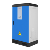
A:the Installation location of
overflow high water level sensor.
B:the Installation location of
overflow low water level sensor.
1. C:the Installation location of pump
dryed high water level sensor.
2. D:Pump outlet,the Installation
location of pump dryed low water
level sensor.
3. S about 1-3 m .
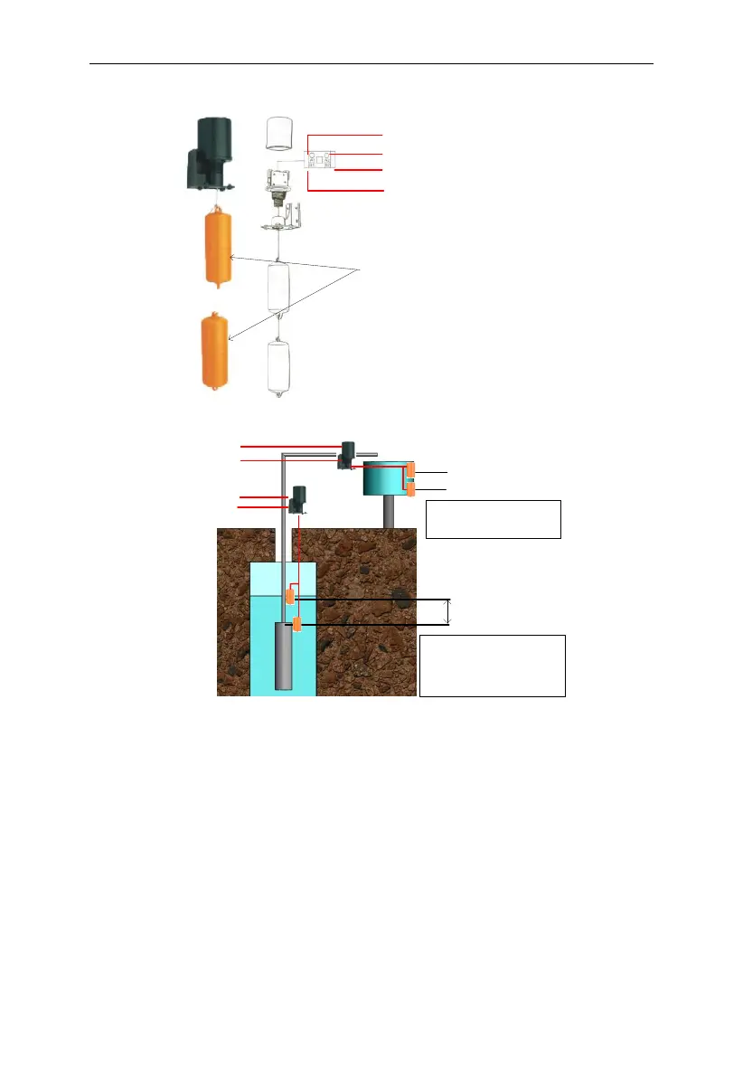
B
To Wa ter le vel
sen sor connecto r
B1 connect To SY
B2 connect to COM
A2 connect to COM
A1 connect to DG