Page 11
John Bean VPI System III Operators Manual
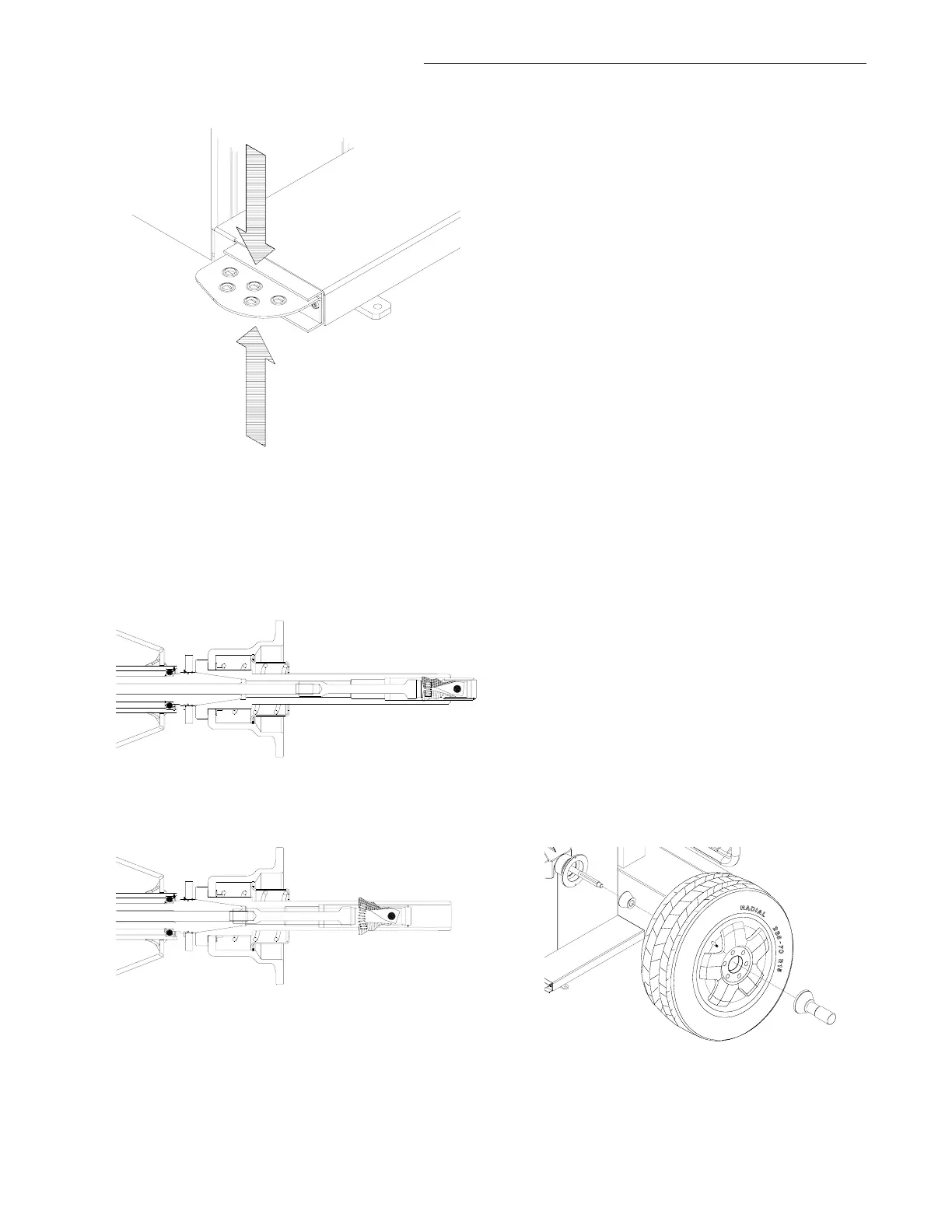
4.2.2 POWER CLAMP OPTION
POWER CLAMP PEDAL
Shaft Lock
The main shaft is locked when the pedal is depressed.
This holds the wheel in the correction position for correct
fitting of the correction weights. See Figure 12a.
This lock is designed only to facilitate orientation of the
wheel and must not be used for braking the main shaft.
Power Clamp Operation.
Lift upward to engage the power clamp jaws when the
lock nut is placed on the shaft.
Lift upward again to release the clamp nut.
NOTE: The first time the unit is operated after power-up,
make sure the power clamp engaging jaws are in the
outer most position and ready for use. An Error of “E14”
may result if the unit cannot accurately determine the
clamping jaw position. Simple press “CANCEL” to
continue, lift the pedal again to cycle and the power clamp
will learn its new position. See Figures 12b and 12c.
1. Mount proper cone against spring plate.
2. Mount wheel on shaft in the same manner as you
would on the car. See Figure 12d
3. Mount the Power Clamp nut along with proper
pressure cup.
4. To operate the power clamp, lift the foot pedal to
engage the clamp. Lift pedal again to release the
nut.
Figure 12a
Figure 12b
Figure 12c
Push down for brake
Lift up for power clamp operation
Power Clamp with jaws all the way OUT
Power Clamp with jaws all the way IN
Figure 12d