Page 12
FAILURE TO TIGHTEN QUICK NUT SECURELY
MAY RESULT IN SERIOUS PERSONAL INJURY.
DO NOT USE A HAMMER TO TIGHTEN THE
QUICK NUT.
TO RELEASE THE QUICK NUT, UNSCREW A FEW
TURNS TO REDUCE THE AXIAL PRESSURE,
THEN PRESS THE UNLOCK LEVER AND SLIDE
AWAY FROM THE SHAFT.
5. Check that the wheel rotates true by turning the wheel
several revolutions while noting any excessive runout.
4.2.3 CENTERING LIGHT-TRUCK WHEELS
An optional offset spacer may be required for some light
truck wheels and reverse-offset wheels that must be
moved away from the balancer mounting flange. The ex-
tension adaptor is often used with the 5-1/4 inch diam-
eter light truck cone.
Install the spacer on the mounting flange, then mount
the wheel, using the front cone method (Figure 13)
Figure 13
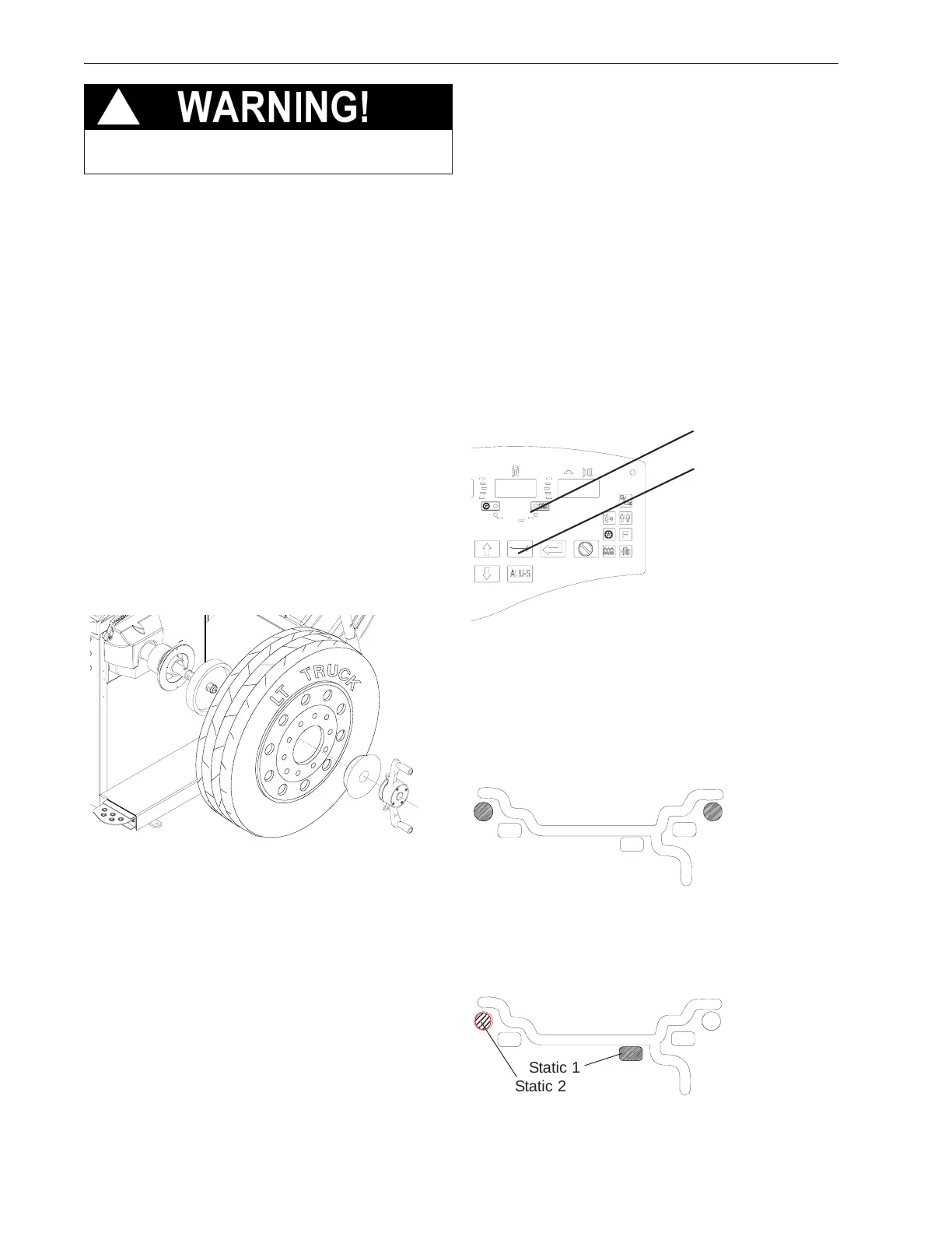
4.3 MODE SELECTION
The majority of balancing takes place in the default 2-
plane dynamic mode which is displayed as "2 PL"
(location 1). Hammer-on clip weights will be placed on
both inside and outside of the rim edge. If required,
select an optional weight placement mode by pressing
the Mode button until the appropriate placement mode
is displayed.
4.3.1 WEIGHT PLACEMENT MODES
Before spinning the wheel (although it may be done af-
terwards) choose the appropriate balancing mode for the
wheel. To select the various placement modes press the
Mode button until placement LEDs indicate desired
placement position.
The balancing modes available are:
A. DYNAMIC (two planes), suggested for all steel rims.
In this case the wheel weights must be clipped onto the
rim edges. This function is selected as a default and
the LEDs corresponding to the wheel weight location
are lit on (Figure 15).
B. STATIC (single plane - Figure 16). Suggested for nar-
row rims (3" or less). Use a single corrective weight placed
in the center or inner edge of rim as illustrated in Figure
16.
Figure 14
Figure 15
Figure 16
!
Mode Button
Indicator LEDs
Static 1
Static 2