Page 22
8.0 SPOKE BALANCING MODE
A standard dynamic balance places compensation weight
in two planes, inner and outer, at the top dead center 180
degrees of each plane of calculated imbalance. Sometimes
the outside weight placement may be unsightly on a cus-
tom wheel. See Figure 34.
The Spoke Mode is designed to “hide” outer plane correc-
tive weight by placing the required weight behind selected
spokes in order to retain the esthetic appeal of the wheel.
1. Press the Alu-s/Spoke button until “SPO” is displayed,
the display will read " SPO " when activated.
2. Enter left plane distance using the SAPE as you would
a dynamic 2-plane or ALU-S balance.
3. When machine displays “d - 2” move the SAPE arm to
the right position plane where weight will be placed.
4. Press Enter, or, lower hood guard. The display will read
“SPO” while spinning. After Braking to a stop rotate the
shaft to the inside plane top dead center position indicated
by the center green LED. Extend the SAPE until the right
reading says “0”, place indicated weight in the position di-
rected by the SAPE.
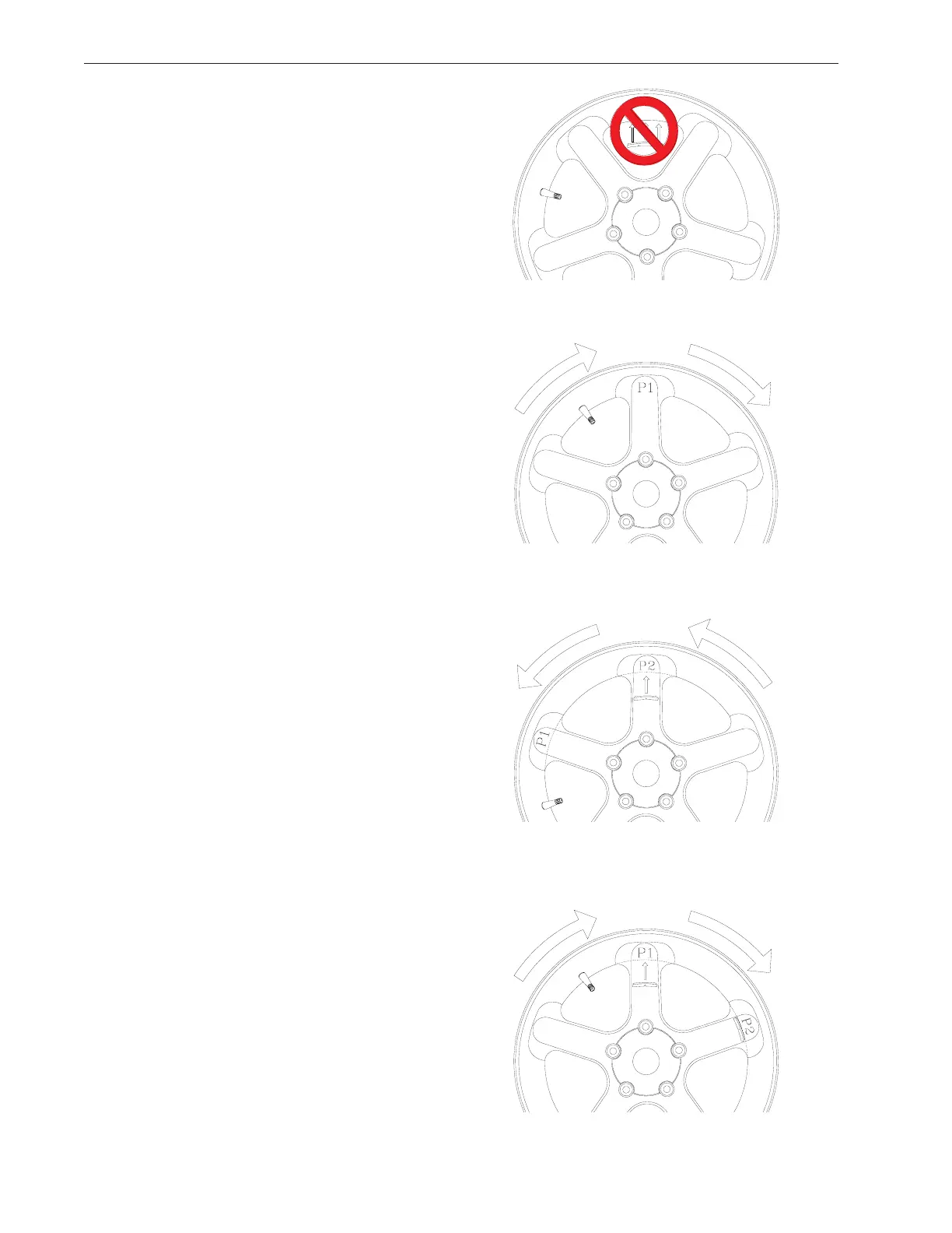
5. Rotate the wheel to the outside plane top dead center
position indicated by the center green LED, press the "F"
button to indicate top dead center.
NOTE: Mark the tire to assist in referencing the corrective
weight top dead center.
6. The display will read "SPO I “. Locate the first spoke
nearest to top dead center and rotate the wheel so that
spoke is at top dead center. See Figure 34. Press F to
store first position.
7. The display will read “SPO 2 “. Locate the second
closest spoke to top dead center and rotate the wheel to
the top dead center position, press F Button again to store
the position. See Figure 35.
8. The display will read “P -2” on its left window and the
balance weight amount in right window. Place the weight
amount displayed at “position 2” behind the spoke, then
rotate the wheel to locate position 1. See Figure 36.
9. When position 1 is located, the balancer will beep. The
display will read “P -1” in the left window and the weight
amount on right window. Place the weight amount dis-
played at “position 1” behind the spoke.
10. Perform a check spin if desired.
Figure 34
Figure 35
Figure 36
Figure 37
X
X
X