Page 20
7.0 ALU-S 2-PLANE MODE
This is a mode similar to ALU mode 2 and 3. The differ-
ence is that the distance and width parameters are ac-
curately defined for a more exacting weight placement,
therefore improving the likelihood of a single spin bal-
ance. Follow the procedures below:
1. Press the Alu-s button to activate the ALU-S 2-PL
mode, the display will read " --- ALU - S 2-PL" when
activated. Each depression of the Alu-s button will toggle
between a 2-plane mode and a single plane mode.
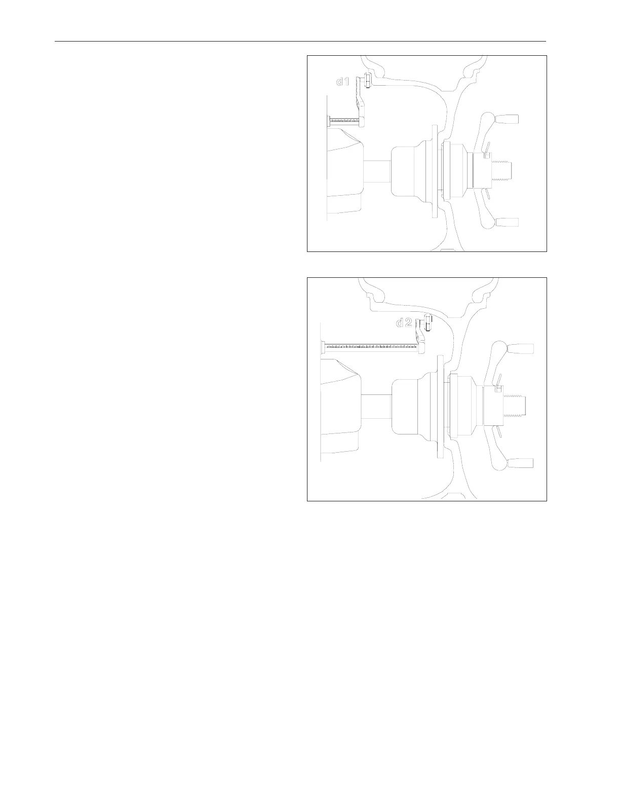
2. Extend the rim offset gauge arm and touch the posi-
tion of the left weight position. See Figure 31. The
display will read “d - I”. The high tone will sound when
dimension is entered. Return the gauge arm to the rest
position, a low pitch tone will indicate when it is OK to
proceed. The width arm is not used in this procedure.
3. Move the parameter arm to the right weight position,
the machine displays “d - 2” as the arm is moved. See
Figure 32. The high tone will sound when dimensions
are entered. Return the gauge arm to the rest position, a
low pitch tone will indicate when it is OK to proceed.
4. Lower the wheel guard or press “Enter” to spin the
wheel. The display will read “ALU” during the spin cycle.
5. After spinning, The wheel/tire assembly will stop with
the outside (right) imbalance plane at top. The display
reads both the left and right plane imbalance weight
and position.
6. Extend the gauge arm to locate the outer place im-
balance. The right display shows the weight amount to
be applied, the left display shows the distance the gauge
arm has to travel to get to the correction plane. The
sape arm will lock when the correct position is reached,
at the same time the display will read “0“ when the proper
position is attained. A “beep” will accompany the lock
position. Apply the weight amount indicated using the
tape weight applicator mounted on the SAPE exten-
sion.
Return the gauge arm to its home position.
7. The left plane correction weight will be applied next
as in step 6 above. The steps are:
- Extend the arm until the arm locks into position.
- Position the wheel in the weight application position
- Apply the displayed weight.
NOTE: RETURNING THE GAUGE ARM TO THE
“HOME” POSITION TOGGLES BETWEEN THE LEFT
AND RIGHT CORRECTION PLANE.
NOTE: TO EXIT ALU-S MODE AND RETURN TO TWO
PLANE DYN (DYNAMIC) MODE PRESS “MODE” BUT-
TON. THE MACHINE DISPLAYS "ALU OFF" FOR ONE
SECOND AND THEN ENTERS IDLE STATE IN THE 2-
PL DYN MODE
NOTE: INSPECT THE RIM AND AVAILABLE
WEIGHTS AND USE GOOD JUDGEMENT IN YOUR
SELECTION. WEIGHTS SHOULD NOT INTERFERE
WITH ANY SUSPENSION PARTS OR MAKE CONTACT
DURING ROTATION. IF A WEIGHT DOES MAKE CON-
TACT, USE AN ALTERNATE LOCATION AND SELECT
AN APPROPRIATE MODE.
Figure 31
Figure 32