Page 24
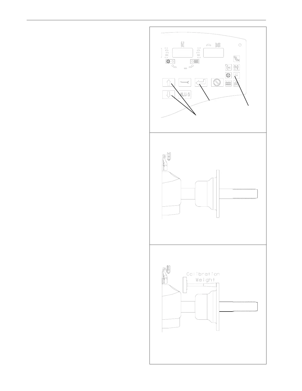
Figure 39
Figure 40
Figure 41
10.0 USER CALIBRATION
F14 Shaft Calibration
The VPI System III Balancer features a user calibration
program which requires only a few minutes to complete.
Perform this procedure when the balancer has been
moved, disturbed, or whenever accuracy is questioned.
Occasional field calibration will ensure years of reliable
service.
Follow these 3 simple steps for shaft calibration:
1. Activate Calibration.
Press the F Button then press the UP/Down buttons
(Figure 39) until the display reads "F" “14”, press EN-
TER
• Once F14 activates, the display will read
"CAL" " GAN" for one second.
• The display will then read "SPN" " 1 ".
2. Spin bare shaft
Lower the wheel guard or press ENTER to spin the shaft.
See Figure 40.
• Displays "CAL" " 1 " as the machine is collecting
data and performing calculations. After taking data,
the shaft is automatically braked to a stopped.
• The display will read "SPN" " 2".
3. Spin shaft with calibration slug on the left side.
Mount calibration slug to inside edge of shaft mounting
plate as shown in Figure 41.
• Lower the wheel guard or press ENTER to spin the
shaft with slug.
• Displays "CAL" " 2" as the balancer is doing its
calculations. When complete, the shaft is automati-
cally braked to a stop.
• The display will read "CAL" "FIN " for one second
when this step of calibration is FINished.
• If for some reason the calibration detected an error,
the display will read: "Err""C__" after the shaft brakes.
NOTE: THE BALANCER WILL NOT FUNCTION UN-
TIL A VALID CALIBRATION HAS BEEN PERFORMED.
AN ERROR MESSAGE WILL BE DISPLAYED IN THE
EVENT PROBLEMS OCCUR DURING THE CALIBRA-
TION PROCESS.
SHAFT CALIBRATION IS COMPLETE
Continue to next page for parameter arm
calibration instructions.
Up / Down
Keys
F Key
Enter Key