Page 15
John Bean VPI System III Operators Manual
4.5 ENTER RIM PARAMETERS
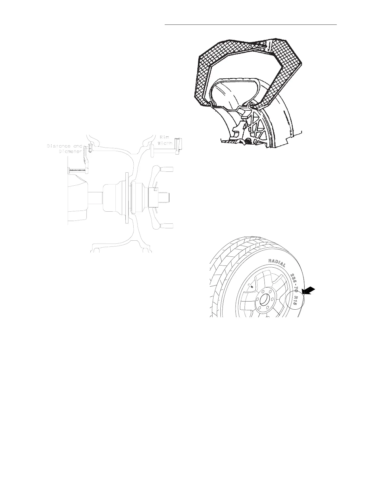
4.5.1 Rim Distance (offset) and Diameter -
Move the rim offset arm to the inside edge of the
rim, touch the pointer to the rim edge, touch the tip
of the width arm to the outside rim edge where
weights will be placed as illustrated in Figure 22.
Hold arms steady for about a second. The beeper
will sound when the parameter values are calcu-
lated and entered automatically. Return the arms
to its home rest position on the balancer. Do not
allow the measurement arms to "dangle".
Figure 22
4.5.2 Manual Parameter Entry
In the event of automatic gauge failure, ANY
parameter value can be input manually.
4.5.2.1 Manual Distance Entry - Move the dis-
tance gauge arm to touch the inner edge of the
wheel where weights are to be placed and observe
the reading on the scale of the distance gauge.
Press manual Wheel Parameter button (#11 page
9) followed by pressing the UP or Down arrow
button until value is displayed in the left display
window.
4.5.2.2 Measure Rim Width Manually using rim
width calipers. Measure wheel where corrective
clip-on weight would be applied, Figure 23. Enter
the measured width by pressing the Parameter
button followed by the UP or Down arrow button
until the desired value appears in the right display.
Figure 23
4.5.2.3 Manual Rim Diameter Entry - Select the
Manual Parameter button. Read the rim diameter
marked on the sidewall of the tire (Figure 24). En-
ter the measured rim diameter by pressing the
Parameter button followed by the UP or Down
arrow button until the desired value appears in the
right display.
Figure 24
NOTE: For a more precise balancing of perfor-
mance wheels, an “ALU-S” Mode is available for
precision determination of wheel parameters. This
feature allows exacting placement of corrective
weights as well. See Page 20 for detailed instruc-
tions.
NOTE: The parameter arms must be in the Home
rest position when the balancer is powered up.
This establishes the arm starting position.