Page 25
John Bean VPI System III Operators Manual
11.0 WIDTH PARAMETER CALIBRATION
F79 Calibration of Width SAPE only
1. Press and release the “F” key toggle the “UP /
DOWN” arrow keys until “F” “79” is displayed
and press enter to activate function of F79. Once
activated the display will change to “CAL” “SAP”
E-2” for 1 second, then the display will change
to“DIS” “tO” “FLA”.
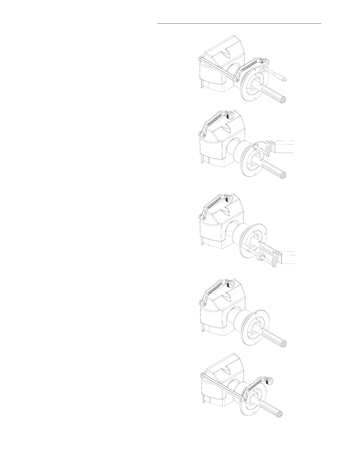
2. Pull the distance gage to the outside flange of the
backing collar, use the flat head of the calibration
weight as an index. After a short beep, the machine
displays “bAC H POS”. Return the arm to ths
rest postition. See Figure 42.
3. The display will read “to FLA NGE”, Touch
the tip of the width gauge to the backing collar and
hold it for one second or press the “F” button
(Figure 42a). The display will change to “bAC “H’
‘POS” followed by a tone. Return the SAPE arm to
the home position.
4. Display will then change to “tO” “CAL” “SLG”.
Screw the calibration weight onto the outside of the
flange. Touch the tip of the width gauge to the tip
of the calibration slug and hold it for one second or
press the “F” button (Figure 43). The display will
change to “SAP” “E-2” “FIN” for one second
followed by a tone indicating a successful calibra-
tion. Unit will then go into an idle state.
WIDTH SAPE CALIBRATION COMPLETE
11.1 PARAMETER CALIBRATION
F80 Distance, Diameter and Width SAPE Calibra-
tion
1. Make sure the SAPE arm is in the home position
as shown in (Figure 44).
NOTE: WEIGHT TRAY MUST BE INSTALLED
2. Activate the gauge calibration program. Press and
release the F key and toggle the “UP / DOWN”
button until 80 is displayed on right display window
and press enter.
3. The right display will read "CAL” “3-D” “SAP" for
one second (Do not move the arm at this point)
this means CALibration SAPE. Then it displays
"SAP” “OUT” “FUL”. The SAPE calibration
procedure is activated.
Figure 42a
Figure 43
Figure 44
Figure 45
Figure 42