26
FORM 145.32-IOM5
ISSUE DATE: 04/08/2019
SECTION 1 – INSTALLATION
LD27707
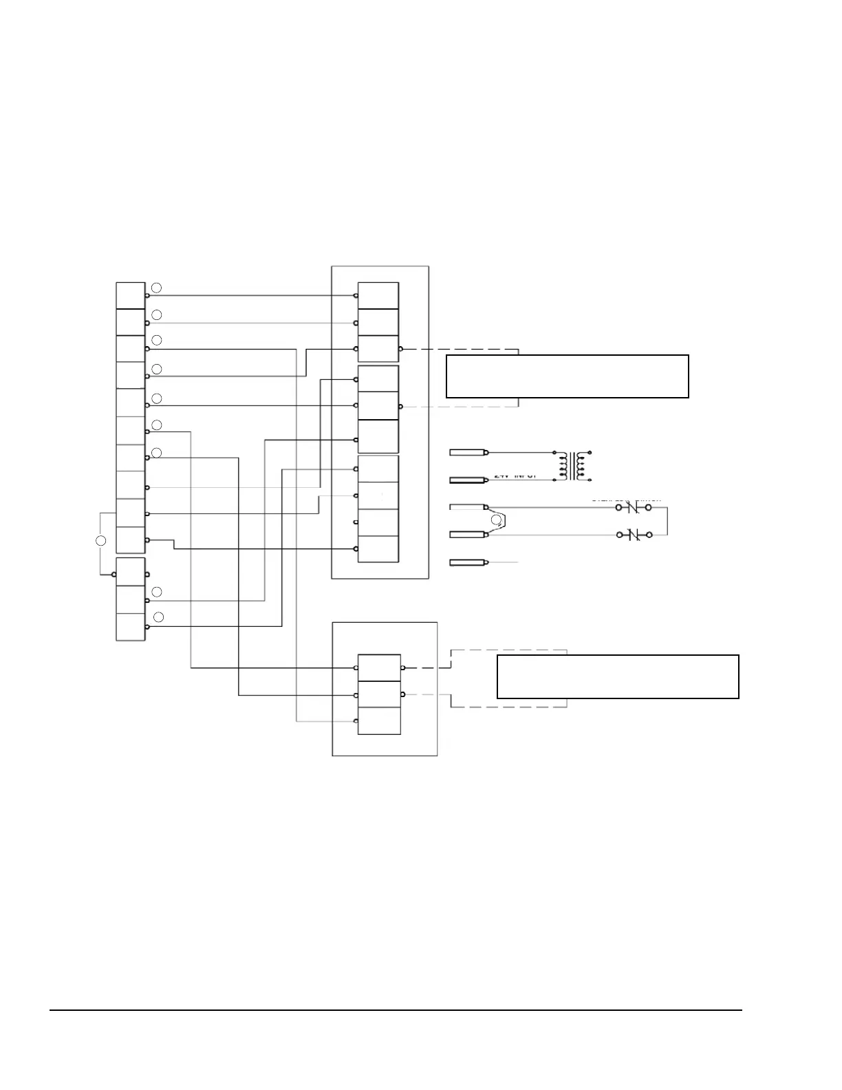
FIGURE 16 - TYPICAL CONTROL DIAGRAM FOR THREE STAGE COOLING (DSH120C)
Optional field installed jumper is required if desired to
change the unit logic to a two stage cooling operation
Optional field installed jumper is required if desired to
change the unit logic to a two stage cooling operation
Terminals on a
Limited Number of
Thermostats
Expansion Board
Terminal Block
Common
24V Input
TRF
Standard Jumper
(If No Options)
Optional Condensate
Overflow Switch
Optional Smoke
Detector
24V Input
24V
SD–24
SD–R
C
6
X
OCC
RC
C
R
G
Y1
W2
W1
W3
Y2
Y3
X
R
SD
C
OCC
G
Y2
Y1
W2
W1
W3
Y4
Y4
Y3
2
2
1
3
4
5
1
1
Thermostat
Terminals
2
2
Main Control
Terminal Block
R
NOTES
1. Unit is capable of supporting up to three stages of discrete heating.
2. Unit is designed to support three stages of discrete cooling.
3. Jumper is required for any combination of R, RC, or RH.
4. OCC is an output from the thermostat to indicate the occupied condition.
5. X is an input to thermostat to display the error status.
6. Jumper is required if no option is installed between SD-24 and SD-R.