39
FORM 145.32-IOM5
ISSUE DATE: 08/30/2018
2
SECTION 2 – STARTUP AND OPERATION
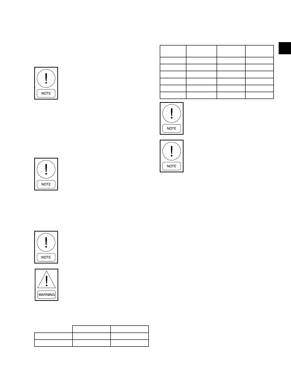
TABLE 24 - REFRIGERANT CHARGE (LBS)
UNIT
NUMBER OF
CIRCUITS
CIRCUIT 1 CIRCUIT 2
DSH024C 1 7.7 -
DSH036C 1 8.9 -
DSH048C 1 11.8 -
DSH060C 1 12.2 -
DSH096C 2 11.4 11.65
DSH120C 2 16 16.2
Factory split and charged units are
charged with two-thirds in condenser and
one-third in evaporator module.
Always charge with liquid when adding
R-410A refrigerant. Failure to do so com-
promises the properties of the refrigerant
being added to the rooftop unit and results
in substandard performance of the unit.
Checking Superheat and Subcooling
R-410A temperature charts list the associated satura-
tion temperature in one column and the associated pres-
sure in another column. See Table 25 on page 40.
Subcooling
When the refrigerant charge is correct, there is no va-
por in the liquid sight glass with the system operating
under full load conditions.
The subcooling temperature of each system can be
calculated:
1. Record the temperature of the liquid line at the
outlet of the condenser.
2. Subtract it from the saturation temperature listed in
Table 25 for the corresponding discharge pressure.
3. If the rooftop unit lacks an access port for liquid ac-
cess, subtract the condenser coil pressure drop value
from Table 25 from the discharge pressure to deter-
mine the equivalent saturation temperature.
For example, when the discharge pressure is 388 psig
and the liquid line temperature is 95.0°F:
• Liquid Pressure = Discharge Pressure (388 psig)
minus 33 psig = 355 psig
• Saturation Temperature for 355 psig = 108.0°F
Start the unit and check the rotation of fans and com-
pressors. Scroll compressors only compress in one
rotational direction. Refer to the Startup and Perfor-
mance Checklist (Form 145.13-CL1).
Prior to startup, it is important to ensure
proper compressor and fan rotation di-
rection is achieved when the system is
installed and operated.
To ensure proper unit operation, monitor the microproces-
sor board for any fault codes. Verify the proper compres-
sor direction by observing that, when the compressor
energizes, the refrigerant suction pressure drops and
the refrigerant discharge pressure rises. Reverse com-
pressor rotation also results in an elevated sound level
and a substantially reduced current draw. Both refriger-
ant pressures are close to equal pressure.
Ensure evaporator motor rotation is cor-
rect upon unit start-up. Switch any two
wires at contactor if blower rotation is
not correct.
If opposite rotation is noticed, disconnect and reverse
any two leads of the three phase supply. Reconnect the
power. If one component is operating in the wrong di-
rection, then all other three phase components on the
unit may be operating in the same phase.
Observe unit operation and check for
unusual noise or vibration.
The air conditioning section of this
equipment is charged with R-410A, a high
pressure refrigerant. Only qualied techni-
cians, using appropriately pressure rated
test instruments, should perform trouble-
shooting or service on this equipment.
TABLE 23 - PRESSURE SWITCH SETTINGS – ALL
MODELS
HIGH LOW
Cut Out (psig) 600 68
Cut In (psig) 450 107