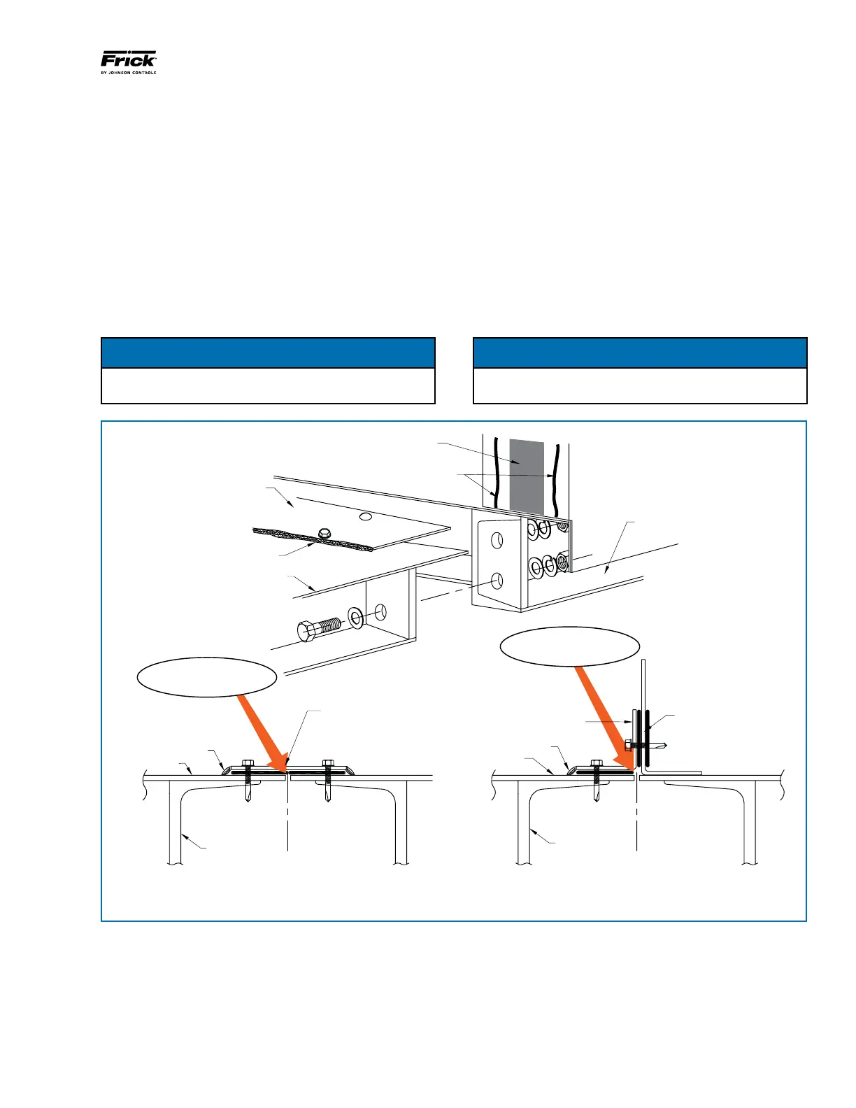
When two AcuAir unit sections are drawn together the base
channels of the two sections form an uninsulated cavity that
under certain conditions could produce condensation. AcuAir
provides a ship loose foam insulation kit to ll this cavity as
part of the reconnect procedure.
The insulation may be injected either from the top of the
cavity prior to installing the reconnect split cover strip, or
from underneath the unit provided the reconnect joint is not
positioned directly over a support structure cross member.
BASE CHANNEL
SPLIT COVER
BASE SKIN
CAULK EDGE OF COVER
AFTER ANCHORING
CAULK
CAULK
BASE SKIN
BASE CHANNEL
INTERNAL WALL
C
L
SPLIT
GASKET
SPLIT COVER
SIDE VIEW WHEN INTERNAL WALL
IS AT A SPLIT.
SPLIT COVER
CAULK
BASE SKIN
BASE CHANNEL
C
L
SPLIT
TYPICAL JOINT OF TWO SECTIONS
WITH FLAT SURFACES
Inject Foam Prior to
Installing Cover
Inject Foam Prior to
Installing Cover
Follow the instructions provided by the foam manufacturer
for preparing the two part foam mixture and the injection kit.
Take special note of the 30 second inactivity limit after which
the injection nozzle may become permanently clogged.
Foam should be injected into the cavity at a rate of 3-4 brd-
ft per linear foot of seam. This will mean a 15 brd-ft can of
expanding foam will ll between 4-5 linear feet of AcuAir
reconnect seam.
When lling the reconnect seam from the top (inside the
AcuAir unit), it may be advisable to cover the bottom of the
opening with duct tape to prevent the foam from dropping
out before it has a chance to expand and attach itself to the
cavity walls.

 Loading...


