System 450™ Series Control Module with Ethernet Communications Installation Instructions 11
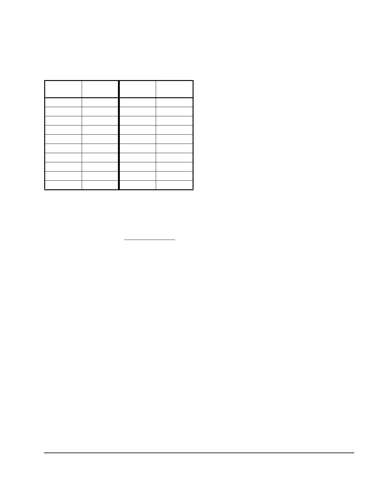
Use Table 5 to determine the negative PSI setup value
that corresponds to your InHg target value. For
example, if you want a relay output to go off when the
sensed pressure reaches 7 InHg, you select the value
-3.5 (psi) in the output’s Relay OFF Selection screen.
Note: When an output references the P 110 Sensor
Type and the output is set up for Differential Control
(Sn-1 and Sn-2 are P 110 Sensor Type), the negative
pressure values displayed in the differential pressure
System Status screen (dIFP) appear as negative psi
values, not InHg values. See Differential Control
for
more information.
Binary Input Control for Relay Outputs
You can connect a binary input (dry contacts) to any of
the three System 450 communications control module
inputs (Sn1, Sn2, or Sn3) and control the output relays
in your control system based on the binary input’s state
(open or closed).
A sensor (Sn-1, Sn-2, or Sn-3) set up as a binary input
can only be referenced by a relay output. Sensors set
up as binary inputs are not available for selection on
analog outputs.
When a relay output references a sensor that is set up
as a binary input, the On and OFF parameter screens
are not available as you set up the output. The relay
output’s On/Off state is controlled by the binary input’s
Closed/Open state and any of the timer parameters
(ONT, OFFT, ONd, or OFFd) that you set up for the
relay output. Refer to the Binary Input Control for Relay
Outputs section on page18 of the System 450 Series
Modular Control Systems with Communications
Control Modules Technical Bulletin (LIT-12011826) for
more information.
High Input-Signal Selection
System 450 control modules with communications
include the High Input-Signal Selection control feature.
The High Input-Signal Selection feature enables a
System 450 control system to monitor a condition
(temperature, pressure, or humidity) with two or three
sensors (of the same type) and control relay and/or
analog outputs based on the highest condition value
sensed by the two or three referenced sensors.
In two sensor applications (HI-2), Sn-1 and Sn-2 must
be the same Sensor Type. In three sensor applications
(HI-3), Sn-1, Sn-2, and Sn-3 must be the same Sensor
Type.
A System 450 control system, using High Input-Signal
Selection, can monitor the outlet pressures of two
condenser coils in a multi-circuit condensing unit using
two pressure sensors of the same type; one connected
to each coil outlet.
Differential Control
System 450 control modules with communications
include the Differential Control feature. Differential
control is used to monitor and maintain a given
difference in a condition (temperature, pressure, or
humidity) between two sensor points within a system,
process, or space.
The Differential Control feature enables a System 450
control system to monitor the temperature, pressure, or
humidity differential between two sensors of the same
type (Sn-1 and Sn-2) and control relay and/or analog
outputs based on the sensed differential value relative
to user-selected differential values (dON, dOFF, dSP,
and dEP).
When a Differential Control sensor (Sn-d) is set up, the
displayed differential sensor value is a calculated
variable value: (Sn-d) = (Sn-1) – (Sn-2).
The Sn-d value appears in the System Status screens
as either a temperature differential value (dIFT),
pressure differential value (dIFP), or humidity
differential value (dIFH). The unit of measurement
associated with the displayed differential value is
determined by the Sn-1 and Sn-2 Sensor Type. See
Table 3 on page 8 for Sensor Types and their units of
measurement.
The relay output setup values dON and dOFF are
condition differential values. When a relay output is set
up for differential control, System 450 controls the relay
state (On or Off) based on the difference between Sn-1
and Sn-2 (Sn-d) relative to the user-selected
differential On (dON) and differential Off (dOFF)
values.
Table 5: InHg Target Values and PSI Setup Values
InHg
Value
psi Setup
Value
InHg
Value
psi Setup
Value
1 -0.5 11 -5.5
2 -1.0 12 -6.0
3 -1.5 13 -6.5
4 -2.0 14 -7.0
5 -2.5 15 -7.5
6 -3.0 16 -8.0
7 -3.5 17 -8.5
8 -4.0 18 -9.0
9 -4.5 19 -9.5
10 -5.0 20 -10.0

 Loading...


