System 450™ Series Control Module with Ethernet Communications Installation Instructions 45
About Page
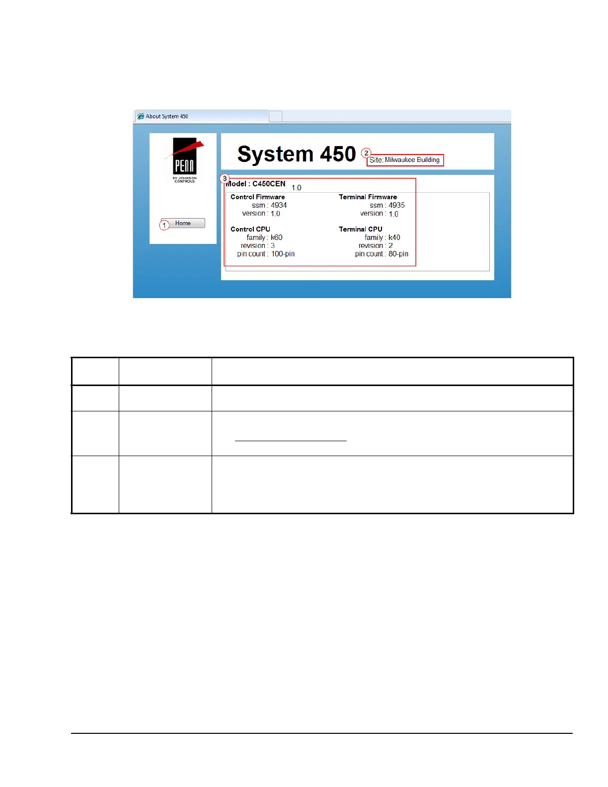
Figure 15 shows an example About Page for a
System 450 control module.
Table 19 provides descriptions, user actions, and/or
references for the items called out in Figure 15.
Table 19: System 450 Web UI Relay Output Configuration Page, User Actions, Descriptions, and
References
Callout
Number
Identifier / Item
Name
User Actions, Descriptions, References
1Home
Button
Click Home to go to the System Overview page.
2Site Name Displays the assigned site name. You can assign a web site name on the Network
Configuration page.
See Network Configuration Page
on page 41 for more information about assigning a site
name.
3Model:
Control Firmware
Terminal Firmware
Control CPU
Terminal CPU
Displays information about the control module model, firmware, and chip set. This
information may be used for identification and advanced troubleshooting by
Johnson Controls PENN product technical support.This information cannot be changed in
the field.
Figure 15: System 450 About Page Example

 Loading...


