System 450™ Series Control Module with Ethernet Communications Installation Instructions10
Setting Up Outputs That Reference a P 110 Sensor
The P 110 Sensor Type can monitor negative pressure
down to 20 InHg (-10 psi). When referencing a P 110
sensor, System 450 displays negative pressure values
in InHg on the Main and System Status screens.
But when you set up an output that references a P 110
sensor and the setup value is a negative pressure
value, you must select a pressure value in negative psi.
Sensor Type Selection Screens: The Sensor Type you select for an input sensor automatically
determines the setup parameters and values for each output that is set up to reference that sensor. See
Table 3 for information about System 450 sensors or transducers, Sensor Types, condition type, units of
measurement, minimum control band or proportional band, setup values, value ranges, and product code
numbers.
Note: For outputs to operate properly, the selected Sensor Type must match the sensor or transducer
model wired to the control module, and the sensor or transducer must be wired to the proper control
module input terminals.
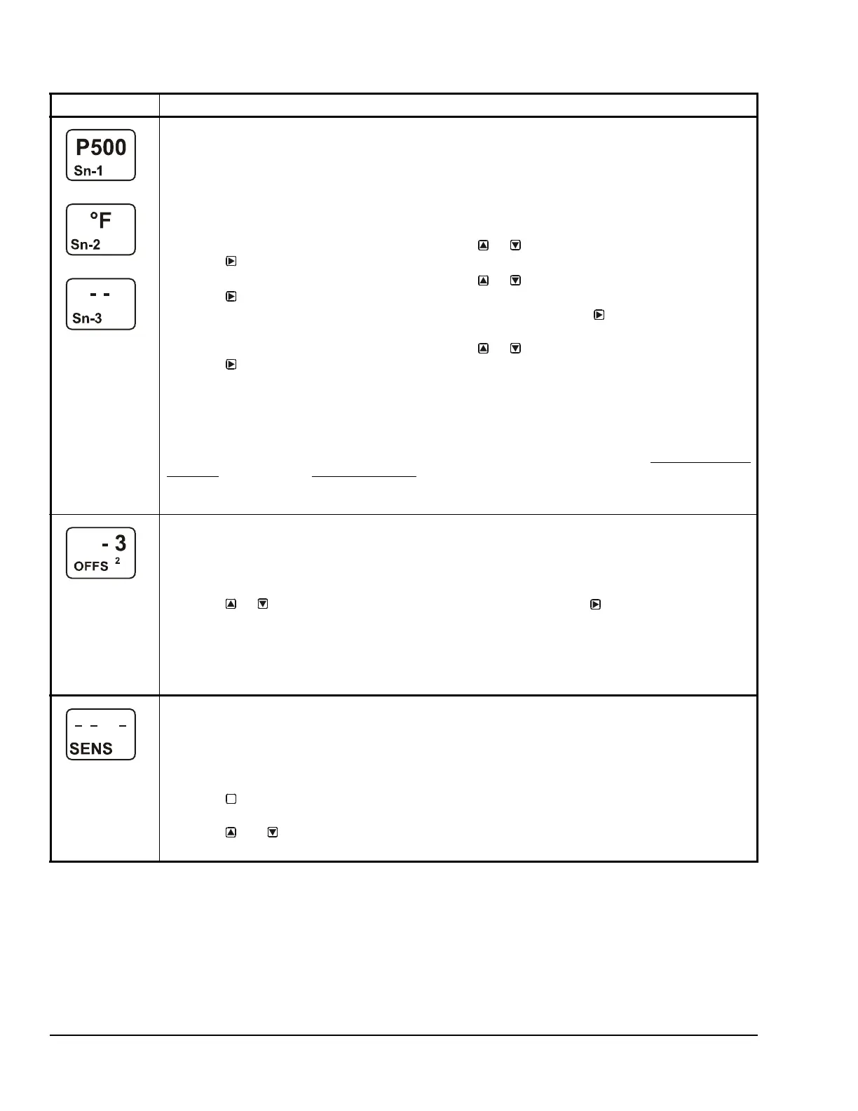
2. In the Sn-1 Sensor Type Selection screen, press or to select the desired Sensor Type.
Press
to save your selection and go to the Sn-2 Sensor Type Selection screen.
3. In the Sn-2 Sensor Type Selection screen, press or to select the desired Sensor Type.
Press
to save your selection and go to the Sn-3 Sensor Type Selection screen.
Note: If your control system does not use three input sensors, simply press
while the two dashes are
flashing in a Sensor Type Selection screen to save no Sensor Type and go to the next setup screen.
4. In the Sn-3 Sensor Type Selection screen, press or to select the desired Sensor Type.
Press
to save your selection and either:
• go to the Temperature Offset Setup screen for the first temperature sensor in your system.
• return to the Sensor Setup Start Screen, if your control system has no temperature sensors.
Note: On System 450 control modules with network communications, if you select the same Sensor
Type for Sn-1 and Sn-2, two additional functional sensors (Sn-d and HI-2) are available for selection
when you set up the control system outputs. If you select the same Sensor Type for Sn-1, Sn-2 and Sn-3,
then functional sensor HI-3 is also available for selection when you set up outputs. See High Input-Signal
Selection on page 11 and Differential Control on page 11 for more information.
The screen examples show Sn-1 with the P 500 Sensor Type selected; Sn-2 with the °F Sensor Type
selected; and Sn-3 with the no Sensor Type selected.
Temperature Offset Selection Screens: Select a temperature offset for the temperature inputs (only) in
your control system.
Sensor Type °F enables an offset of +/- 5°F in 1 degree increments.
Sensor Type °C enables an offset of +/- 2.5°C in 0.5 degree increments.
Note: The temperature offset changes the displayed temperature value by the selected offset value.
5. Press or to select the desired temperature offset value. Press :
• to go to the next Temperature Offset Selection screen (if there are additional temperature
sensors in your control system) and repeat this step for each temperature sensor.
• to return to the Sensor Setup Start screen.
The screen example shows an OFFS value of -3 (°F) for Sensor 2. Therefore a sensed temperature value
of 75 (°F) at Sensor 2 is displayed as 72 (°F).
Sensor Setup Start Screen: When you have finished setting up all of the sensors for your control
system, the display returns to the Sensor Setup Start screen.
Note: You can edit the sensor setup values at any time, if required. However, changing the Sensor Type
for a sensor that is referenced by an output requires setting up the output again to the new Sensor Type
values.
After the sensors are set up for your control system, you can:
• Press to scroll through the Output Setup Start screens and begin setting up your system
outputs.
• Press and simultaneously to return to the Main screens.
The screen example shows Sensors Setup Start screen with flashing dashes.
Table 4: System 450 Sensor Setup Screen Information and Procedures (Part 2 of 2)
LCD Screen Name, Description or Function, User Action, and Example
M

 Loading...


