System 450™ Series Control Module with Ethernet Communications Installation Instructions 15
Setting Up an Analog Output
Analog outputs provide an analog signal to control
equipment in you application based on the input from a
standard fixed setpoint sensor (Sn-1, Sn-2, or Sn-3) or
a High Input Signal Selection sensor (HI-2 or HI-3).
Note: The differential sensor, Sn-d, is used to set up
analog and relay outputs for Differential Control. See
Differential Control
on page 11 for more information.
Analog outputs provide an auto-selecting analog signal
that is proportional to the sensed input condition. The
System 450 analog output senses the impedance of
the controlled equipment’s analog input circuit and
automatically delivers either a 0–10 VDC or 4–20 mA
signal to the controlled equipment.
Figure 5 shows an example of the analog output setup
values and the resulting output signal in a typical space
heating application (SP > EP and OSP < OEP).
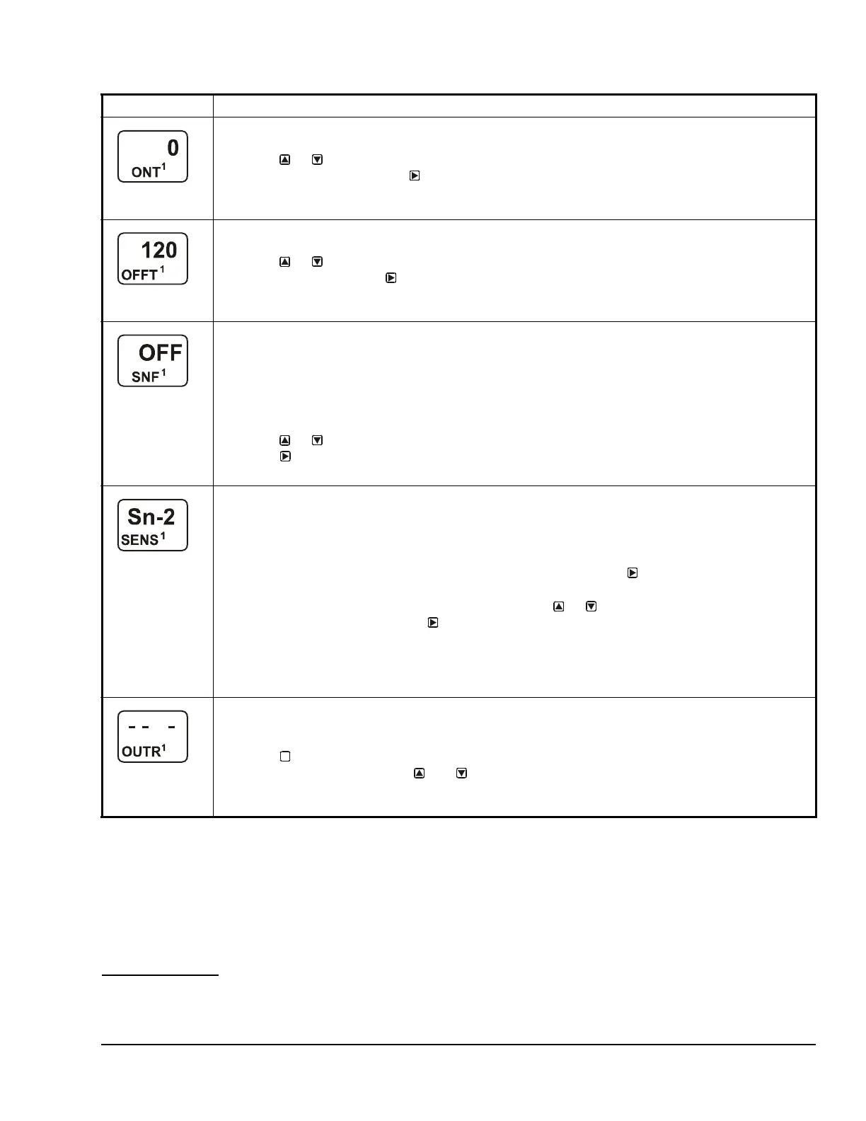
Minimum Relay ON Time Selection Screen: Select the minimum time that the output relay is required
to stay on after it turns on. The minimum ON Time range is 0 to 300 seconds.
7. Press or to select the minimum time that the output relay remains on after reaching the
Relay ON value, then press
to save your selection and go to the Minimum Relay OFF Time
Selection screen.
The screen example shows an ONT value of 0 (seconds) selected for Output 1.
Minimum Relay OFF Time Selection Screen: Select the minimum time that the output relay is required
to stay Off after it turns Off. Minimum OFF Time range is 0 to 300 seconds.
8. Press or to select the minimum time that this output relay remains off after reaching the
Relay OFF value. Press to save your selection and go to the Sensor Failure Mode Selection
screen.
The screen example shows an OFFT value of 120 (seconds) selected for Output 1.
Sensor Failure Mode Selection Screen: Select the output’s mode of operation if a referenced sensor or
sensor wiring fails. For outputs that reference functional sensors HI-2, HI-3, or Sn-d, the failure of any of
the referenced hard-wired sensors results in a functional sensor failure condition. The output operates in
the selected Sensor Failure mode until the failure is remedied. Sensor Failure mode selections for relay
outputs include:
• ON = Output relay remains on during sensor failure.
• OFF = Output relay remains off during sensor failure.
9. Press or to select this output’s mode of operation if the sensor or sensor wiring fails.
Press
to save your sensor failure mode selection and go to the Edit Sensor screen.
The screen example shows OFF selected as the Sensor Failure mode for Output 1.
Edit Sensor Screen: This screen displays the sensor that this output currently references. Typically, no
action is taken in this screen. But if you need to change the sensor that this output references, you can
select a different sensor for this output in this screen.
Note: If you change the sensor that an output references to a sensor with a different Sensor Type, the
default setup values for the output change, and you must set the output up again.
10. If you do not need to change this output’s sensor, simply press to save the current sensor
selection and return to the Relay Output Setup Start screen.
To change the sensor this output references, press or to select the new sensor that this
output references. Then press to save the new sensor selection and return to the Relay ON
Selection screen (ON or dON). If the new sensor has a different Sensor Type from the
previously referenced sensor, repeat the output setup procedure for this output.
This relay output is now set up in the System 450 UI.
The screen example shows Sn-2 is selected Sensor for Output 1.
Relay Output Setup Start Screen
After you have set up this relay output, you can go to another Output Setup Start screen, the Sensor
Setup Start screen, or return to the Main screens.
11. Press to scroll through the remaining Output Setup Start screens and return to the Sensor
Setup Start screen, or press and simultaneously to return to the System 450 Main
screens.
The screen example shows a Relay Output Setup Start screen for Output 1.
Table 7: System 450 Setup Screen Information and Procedures for Relay Outputs (Part 4 of 4)
LCD Screen Name, Description or Function, User Action, Example
M

 Loading...


