System 450™ Series Control Module with Ethernet Communications Installation Instructions14
OR
When a relay output references Sn-1, Sn-2, Sn-3, HI-2, or HI-3, the Standard Relay OFF Selection
screen appears.
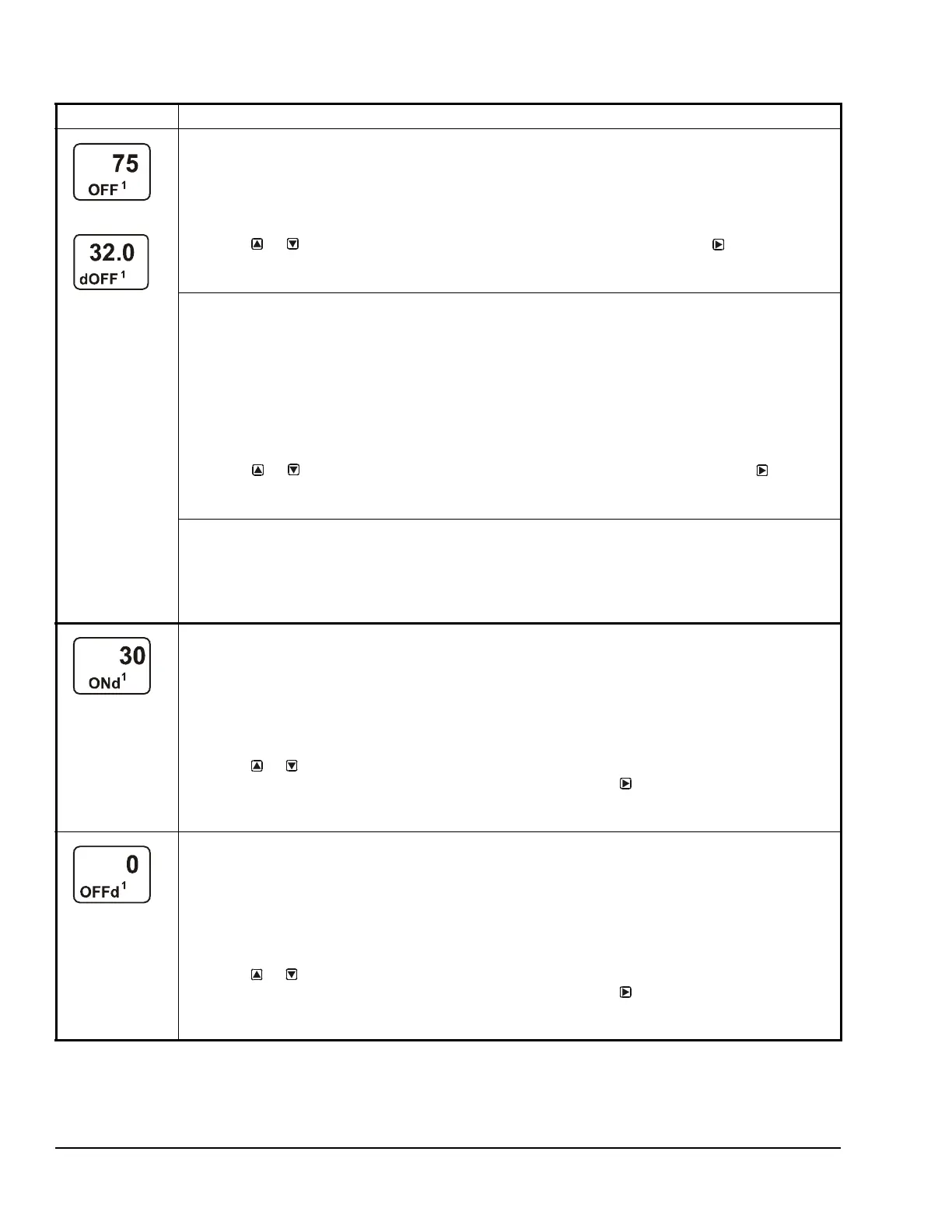
Standard Relay OFF Selection Screen: Select the value at which the relay turns off. Relay OFF is
defined as relay LED Off, relay contacts N.C. to C are closed, and N.O. to C contacts are open.
Note: The value ranges and minimum control band are determined by the Sensor Type selected for the
sensor that the output references and are enforced in the Relay ON and Relay OFF Selection screens.
4. Press or to select the value at which output relay turns off, then press
to save your
selection and go to Relay-ON Delay Time Selection screen.
The screen example shows an OFF value of 75 (°F) selected for Relay Output 1.
When a relay output references Sn-d, the Differential Relay dOFF Selection screen appears.
Differential Relay dOFF Selection Screen: Select the dOFF value at which the relay turns on. The
dOFF value is a differential value that represents the intended difference in the condition (temperature,
pressure, or humidity) between Sn-1 and Sn-2 (Sn-1 minus Sn-2) at which the relay is turned off.
Depending on the intended control action and the physical location of Sn-1 and Sn-2 sensors in the
condition process, dOFF may be a positive or negative value. dOFF is defined as relay LED Off, relay
contacts N.C. to C are closed, and N.O. to C contacts are open.
Note: The unit of measurement, resolution increment, minimum control band, and range of usable
values for dON and dOFF are determined by the Sensor Type selected for Sn-1 and Sn-2. (See Table 3
and Table 6 for more information.)
4. Press or to select the differential value at which output relay turns off. Press to save
your selection and go to the Relay-ON Delay Time Selection Screen.
The screen example shows a dOFF value of 32 (psi) selected for Relay Output 1.
When a Relay Output references a hard-wire sensor (Sn-1, Sn-2, or Sn-3) that is set up with the bin
(binary input) Sensor Type, the ON and OFF screens are not available. If you select and save a
sensor set up as a binary input in Step 2, the ON Delay (ONd) screen appears. Go to Step 5.
Binary Input Control: Relay outputs that reference a sensor set up with the bin Sensor Type are
controlled by the binary input contacts state (open or closed). The ON and OFF values are not used to
control relay outputs that reference a binary input sensor.
Relay-On Delay Time Selection Screen: Select the value (in seconds) that you want output relay to
delay turning ON after the condition reaches and maintains the Relay On value. The Relay-On Delay time
range is 0 to 300 seconds.
Note: The Relay-On Delay feature can be used to delay the output relay from going to the On state after
the On value is reached at the referenced input sensor. The condition change must reach or exceed the
output's Relay On value for the entire duration of the Relay-On Delay, before the output relay goes On.
This feature can be used to prevent controlled equipment such as actuators from being exercised every
time the condition momentarily spikes to the Relay-On value, reducing wear on the controlled equipment.
5. Press or to select the time value (in seconds) that the output relay delays turning on after
the process condition reaches the Relay-On value, then press
to save your selection and go
to the Relay-On Delay Time Selection Screen.
The screen example shows an ONd value of 30 (seconds) selected for Output 1.
Relay-Off Delay Time Selection Screen: Select the value (in seconds) that you want output relay to
delay turning Off after the condition reaches and maintains the Relay Off value. The Relay-Off Delay time
range is 0 to 300 seconds.
Note: The Relay-Off Delay feature can be used to delay the output relay from going to the Off state after
the Off value is reached at the referenced input sensor. The condition change must reach or exceed the
output's Relay Off value for the entire duration of the Relay-Off Delay, before the output relay goes Off.
This feature is used to prevent controlled equipment such as actuators from being exercised every time
the condition momentarily spikes to the Relay Off value, reducing wear on the controlled equipment.
6. Press or to select the time value (in seconds) that the output relay delays turning off after
the process condition reaches the Relay Off value, then press
to save your selection and go
to the Relay-Off Delay Time Selection Screen.
The screen example shows an OFFd value of 0 (seconds) selected for Output 1.
Table 7: System 450 Setup Screen Information and Procedures for Relay Outputs (Part 3 of 4)
LCD Screen Name, Description or Function, User Action, Example

 Loading...


