System 450™ Series Control Module with Ethernet Communications Installation Instructions12
When an analog output is set up for differential control,
System 450 controls the analog signal strength based
on the difference between Sn-1 and Sn-2 (Sn-d)
relative to the user-selected differential setpoint (dSP)
and differential endpoint (dEP) values.
Differential Sensor Range of Usable Values
The System 450 Differential Control sensor (Sn-d)
value is always equal to Sn-1 minus Sn-2. Depending
on the intended control action of the output, the
differential value may be either a positive or negative
value. Therefore, the range of usable values is twice as
large as a single sensor, and each Sensor Type has an
equal number of positive and negative values. See
Table 6 for the range of usable values when an output
references Sn-d.
Note: Binary Inputs cannot be set up to as a
Differential Sensor.
Setting Up System 450 Outputs
After you build and connect power to your control
system module assembly, the output numbers and
output types for your control system are automatically
assigned in the UI.
Note: You must set up the input sensors for your
control system before you can set up the outputs. See
Setting Up System 450 Sensors
on page 8 for more
information.
To set up System 450 outputs in the UI:
1. Apply power to your module assembly. After the
Startup screen appears briefly (displaying the
control module firmware version), the Main screen
appears on the LCD.
2. In the Main screen, press and hold
and
simultaneously for 5 seconds to access the setup
screens and to go to the Sensor Setup Start
screen.
3. At the Sensor Setup Start screen, press
repeatedly to scroll through and select the desired
Output Setup Start screen. The Output Setup
Start screen indicates the output number and the
output type for the selected output.
4. To set up relay outputs, see Setting Up a Relay
Output and Table 7 for setup information and
procedures.
5. To set up analog outputs, see Setting Up an Analog
Output and Table 9 for setup information and
procedures.
Setting Up a Relay Output
Table 7 provides information, procedures, guidelines,
and screen examples for setting up relay outputs on
System 450 control modules with communications.
See Figure 6 on page 25 for example menu flow of the
Relay Output 1 set up in Table 7.
Note: The differential sensor, Sn-d, is used to set up
analog and relay outputs for Differential Control. See
Differential Control
on page 11 for more information.
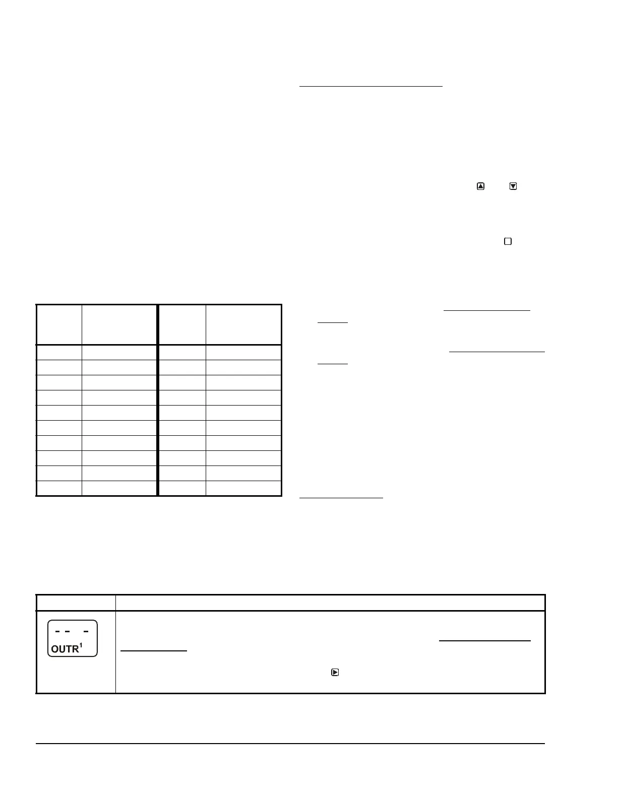
Table 6: Ranges of Usable Values for Sensor
Types in Differential Control Applications
Sensor
Type
Sn-d Range
of Usable
Values
Sensor
Type
Sn-d Range
of Usable
Values
F -290 to 290 P 30 -30.0 to 30.0
C -161.0 to 161.0 P 50 -50.0 to 50.0
rH -95 to 95 P 100 -100.0 to 100.0
P0.25 -0.500 to 0.500 P 110 -110.0 to 110.0
P 0.5 -0.500 to 0.500 P 200 -200 to 200
P 2.5 -2.50 to 2.50 P 500 -500 to 500
P 5 -5.00 to 5.00 P 750 -750 to 750
P 8 -9.00 to 9.00 HIF -380 to 380
P 10 -10.00 to 10.00 HIC -210.0 to 210.0
P 15 -16.0 to 16.0 -- --
M
Table 7: System 450 Setup Screen Information and Procedures for Relay Outputs (Part 1 of 4)
LCD Screen Name, Description or Function, User Action, Example
Relay Output Setup Start Screen: The output numbers and the output type (relay or analog) are
determined by the module types and configuration of your control system’s module assembly and are
automatically assigned when you connect power to the module assembly. (See Setting Up the Control
System in the UI on page 5.)
Note: You must set up the control system input sensors before you can set up the outputs.
1. In the Relay Output Setup Start screen, press
to go to the output’s Sensor Selection screen.
The screen example shows a Relay Output Setup Start screen for Output 1.

 Loading...


