System 450™ Series Control Module with Ethernet Communications Installation Instructions26
Setting Up Ethernet Communications
Obtain the information in this section and record the
values in the fields provided. Your network
administrator may be able to provide most, if not all, of
this Ethernet setup information. Use the following steps
to connect your computer to the router using a wired
port or Wi-Fi:
1. Consult the user manual for the router or see your
Network Administrator to obtain the router IP
address, user name, and password.
• Record the router’s Internal LAN IP address
(____.____.____.____).
• Record the user name (__________) and
password (__________).
2. Log in to the router using the router’s IP address
and login credentials from Step 1. Access the
configuration and setup pages within the router.
3. Locate the router’s LAN setup screen to view the
router’s subnet mask.
Note: The subnet mask is usually 255.255.255.0.
• Record the router’s subnet mask
(____.____.____.____).
4. Determine the DHCP client address range used by
the router. You can use addresses outside this
DHCP address range for static addressing.
Note: If the DHCP client address range does not
provide space for the devices you need to add to the
network, reduce the DHCP client address range.
• Record the DHCP client address range
(____.____.____.____ to
____.____.____.____).
5. Determine if there are any existing devices on the
network that use a static IP address. Examples
might include printers, cameras, or other special
equipment.
6. Determine the static address range. The static
address range does not fall within the DHCP client
address range and does not conflict with any
existing devices that use a static IP address. For
example, if the DHCP client address range is
192.168.1.2 to 192.168.1.100, the space available
for static IP addressing would be 192.168.1.101 to
192.168.1.255.
• Record the static address range
(____.____.____.____ to
____.____.____.____).
Establishing a Direct Connection
The Ethernet control module is shipped with the Direct
Connect addressing mode enabled. When operating in
Direct Connect mode, the control module uses an
integral DHCP server to provide an IP address to your
computer and enables communications between your
computer and the control module.
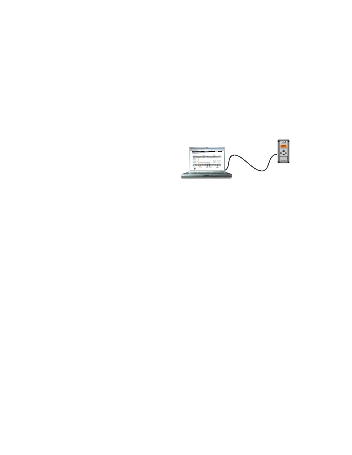
After you have established a direct connection between
your computer and the Ethernet control module
(Figure 7), you can use a web browser on your
computer to browse to the Ethernet control module and
set up the Ethernet control module’s network
configuration before connecting it to an existing local
network.
You can also use the Direct Connection mode to
connect and browse to System 450 communications
control systems that are not permanently connected to
a network.
Note: The control module’s network settings, with the
exception of resetting the network configuration to its
default state, cannot be set up or changed via the local
user interface.
To establish a direct connection between a computer
and a Ethernet control module:
1. Start your computer and disable the wireless
networking feature (Wi-Fi) on the computer.
2. Connect an Ethernet cable (straight-through or
crossover) between your computer’s RJ-45
Ethernet port and the Ethernet control module’s
RJ-45 Ethernet port.
3. Connect power to the Ethernet control module.
Using the local UI, navigate to the Communications
Setup screen and verify that the address mode is
set to Direct (drct). If it is not, navigate to the Reset
Default Network Configuration screen and restore
the network configuration to its default state. See
Table 10 on page 20 for information on navigating
to and through the Communications Setup screen.
Straight-Through or
Cross-Over
Ethernet Cable
PC/Laptop
C450CEN-1
Communications
Control Module
Figure 7: Direct Connection Between a Laptop and
a System 450 Communications Control Module

 Loading...


