System 450™ Series Control Module with Ethernet Communications Installation Instructions6
4. Set up the control system outputs in the UI. See
Setting Up System 450 Outputs
on page 12.
Viewing the Startup, Main, and System Status
Screens
Every time you connect power to a System 450 control
module, the Startup screen appears for several
seconds before the Main screens appear. The Startup
screen displays the current firmware version for the
module. See Table 2 and System 450 Firmware
Versions for more information.
After you install, wire, power on, and set up your control
system in the UI, the Main screens appear on the LCD,
immediately after the Startup screen. During normal
operation, the Main screens automatically scroll
through the current status of each sensor in your
control system. See Table 2 for more information.
The System Status screens display the current status
of each input and output in your control system. With
the Main screen displayed, press repeatedly to scroll
through and view all of the status screens in your
control system. See Table 2 for more information about
the System Status screens.
System 450 Firmware Versions
System 450 firmware versions identify the features
available on System 450 modules. System 450 control
modules with network communications have the High
Input-Signal Selection and Differential Control features.
See High Input-Signal Selection
and Differential
Control on page 11 for more information.
Accessing the System 450 Setup Start Screens
Access the System 450 Setup Start screens from the
Main screen. See Table 2 for more information about
the Setup Start screens.
To access the System 450 setup screens:
1. Apply power to your module assembly. After the
Startup screen appears briefly (displaying the
control module firmware version), the Main screen
appears on the LCD.
2. In the Main screen, press and hold
and
simultaneously for 5 seconds to access the setup
screens and go to the Sensor Setup Start screen.
3. Press
repeatedly to scroll through the Output
Setup Start screens. See Figure 6.
Note: The UI returns to the Main screens after 2
minutes of inactivity in any screen in the UI.
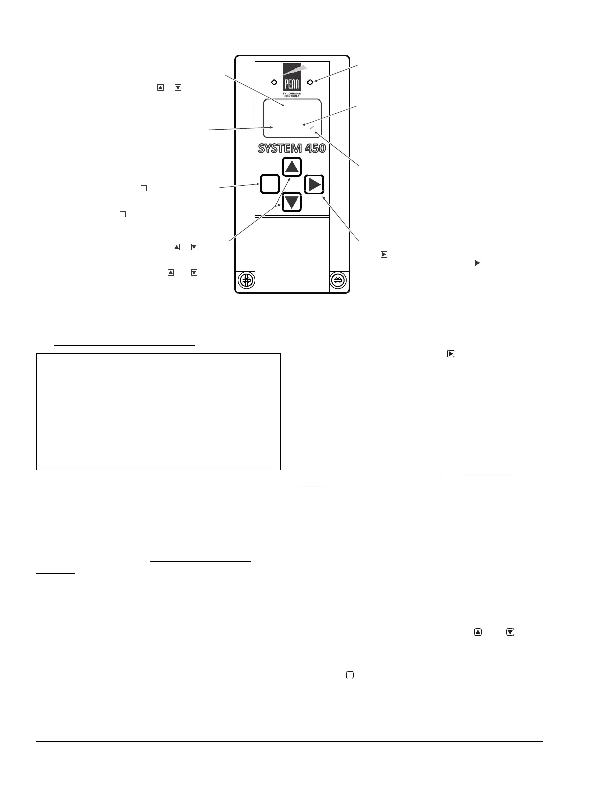
Figure 4: System 450 Communications Module LEDs, LCD, Four-Button Touch Pad User Interface
FIG:sys450_ethernet_module_ui
100
OSP
Displays a numerical
value that identifies the output associated
with the status or setup value shown
on the screen. Output numbers are
automatically determined by the outputs'
physical positions (left to right) in the
module assembly. (Here, 4 = Output 4.)
Control Ramp Icon:
Displays whether an
analog output (only) is set as direct acting
or reverse acting, and whether the output
signal strength is at minimum or maximum
when the sensed property is at Setpoint.
The control ramp icon displayed is
determined by the output's SP, EP, OSP,
and OEP setup values.
Menu Button:
Press to move through the
sensor and output setup start screens.
When moving through the status or setup
screens, press to return to the status start
screen or setup start screen.
M
M
Status or Setup Identifier:
or
OSP
Displays the
unit of measurement, output, sensor number,
setup parameter for the displayed status or
setup value. (Here, the setup identifier
represents % output signal strength at setpoint.)
Up and Down Buttons:
Press or to select
a different value for any flashing value in the
setup value field. In the Main (sensor status)
screens, press and hold both and for
5 seconds to access the Setup Start screens.
Status or Setup Value:
or
Displays the current
input status, output status setup parameter
value for the displayed input sensor, output
or setup parameter. select
a different parameter value when the value
is flashing. (Here, 100 = 100%.)
Press or to
LED:
The green LEDs on the Comm
Module indicate Ethernet communications
performance on the Ethernet network.
Blinking Right LED = proper receive activity
Blinking Left LED = proper transmit activity
Next Button:
press to scroll through the system status
screens. In a setup screen, press to save
the (flashing) setup value and go to the
next setup screen.
IMPORTANT: Do not change the module positions
after a System 450 control system is set up in the UI.
System 450 control logic is set up in the UI according
to the Sensor Types, the output types, and the output
numbers. Changing modules or module positions in a
module assembly that is already set up in the UI can
change the output numbers, output types, and the
setup values of the assembly outputs, which requires
setting up the outputs again.
M

 Loading...


