System 450™ Series Control Module with Ethernet Communications Installation Instructions 7
Table 2: System 450 Startup Screen, Main Screens, Status Screens, and Setup Start Screens Information
and Procedures (Part 1 of 2)
LCD Screen Name, Description or Function, User Action, and Example
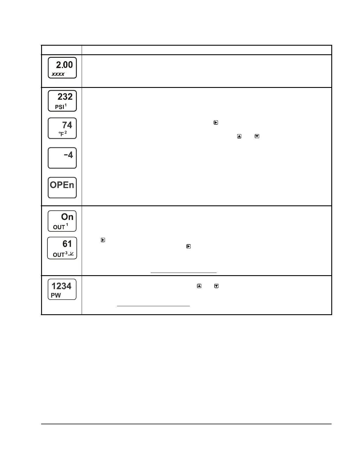
Startup Screen: When you power a System 450 control module, the LCD displays the control module’s
current firmware version for approximately five seconds before it displays the Main (Input Status) screen.
The screen example shows System 450 firmware version number 2.00 on the top of the screen. The
number on the bottom of the screen (indicated in this example with xxxx) identifies the Johnson Controls
firmware.
Main (Input Status) Screens: During normal operation, the Main screens automatically scroll through the
current status of each input sensor in your control system and display the sensor number, the unit of
measurement, and the sensed condition value. See Figure 6 for an example of the Main screens.
Note: Main screens are view-only; selections are not made in Main screens. The Main screens are the
System 450 default screens. After 2 minutes of inactivity in any screen, the UI reverts to the Main screens.
While the Main screens are scrolling, you can press
repeatedly to scroll through and view the
System Status screens for all inputs and outputs in your control system.
While the Main Screens are scrolling, you can press and hold
and for 5 seconds to access
your control system’s Setup Start screens. But, if the System 450 User password is set to a value
other than factory-default value of 0000, the Password Protected Access screen appears and
requires you to enter either the valid User password or valid Admin password to proceed to the
Sensor Setup Start screen and the rest of the System 450 setup screens.
The top two screen examples show Sensor 1 sensing 232 psi and Sensor 2 sensing 74°F. The third
screen example shows a Temperature Differential Sensor sensing a -4 degree differential. The bottom
screen shows Sensor 3 set up as a Binary Input and the input is open.
System Status Screens: The System Status screens display current status of all inputs and outputs in
your control system. System Status screens are view-only; selections are not made in Status screens.
Relay output status screens display output number and relay status (On/Off). Analog output status screens
display output number, output signal strength (as a percentage of the total signal strength), and a control
ramp icon, which indicates the output’s control action.
Press
repeatedly to scroll and view the System Status screens for the inputs and outputs in your
control system. When you stop pressing
, the displayed Status screen refreshes its value and
remains displayed for 2 minutes before returning to the Main Screens.
The screen examples show Output 1 relay is On and Output 3 signal strength is 61% of the total signal
strength. The control ramp icon in the bottom screen example indicates that the analog output is set up with
SP<EP and OSP<OEP. See Setting Up an Analog Output for information about ramp icons.
Password Protected Access Screen: When Password Protection is enabled, the Password Protected
Access screen appears after you press and hold
and for 5 seconds to access your control system’s
Setup Start screens. If the User password is set to the factory-default value of 0000, password protection is
disabled, and the Password Protected Access screen does not appear; the Sensor Setup Start screen
appears. See Setting Up Password Protection
on page 21 for more information on System 450 password
protection.
bin

 Loading...


