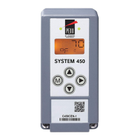
System 450™ Series Control Module with Ethernet Communications Installation Instructions 3
Wiring
See Figure 2 and Table 1 for electrical termination
locations and wiring information. See Technical
Specifications on page 46 for electrical ratings.
WARNING: Risk of Electric Shock.
Disconnect or isolate all power supplies
before making electrical connections.
More than one disconnect or isolation
may be required to completely
de-energize equipment. Contact with
components carrying hazardous voltage
can cause electric shock and may result
in severe personal injury or death.
IMPORTANT: Use copper conductors only. Make
all wiring in accordance with local, national, and
regional regulations.
IMPORTANT: Do not exceed the System 450
module electrical ratings. Exceeding module
electrical ratings can result in permanent damage to
the modules and void any warranty.
IMPORTANT: Run all low-voltage wiring and
cables separate from all high-voltage wiring.
Shielded cable is strongly recommended for input
(sensor) and analog output cables that are exposed
to high electromagnetic or radio frequency noise.
IMPORTANT: Electrostatic discharge can damage
System 450 modules. Use proper Electrostatic
Discharge (ESD) precautions during installation and
servicing to avoid damaging System 450 modules.
IMPORTANT: Do not connect 24 VAC supply
power to the System 450 modules before finishing
wiring and checking all wiring connections. Short
circuits or improperly connected wires can result in
damage to the modules and void any warranty.
IMPORTANT: A System 450 control module and
module assembly can be connected to an internal
power source (a System 450 power module) or an
external power source (24 V power connected to the
24V and COM terminals on the control module), but
must not be connected to both power sources
simultaneously. Connecting a control module to both
internal and external power sources can damage the
modules and void any warranty.
IMPORTANT: When connecting System 450
compatible sensors with shielded cable to a
System 450 control module, connect the cable
shield drain lead to one of the C (common) terminals
on the input sensor terminal block. Do not connect
the shield at any other point along the cable. Isolate
and insulate the shield drain at the sensor end of the
cable. Connecting a cable shield at more than one
point can enable transient currents to flow through
the sensor cable shield, which can cause erratic
control operation.

 Loading...