System 450™ Series Control Module with Ethernet Communications Installation Instructions8
Setting Up System 450 Sensors
You must set up the input sensors for your control
system before you can set up any of outputs. To set up
the input sensors you must access the setup screens.
See Accessing the System 450 Setup Start Screens
.
The Sensor Setup Start screen is the first screen
displayed when you access the system setup screens.
Table 3 provides information about System 450
sensors, Sensor Types, parameter values, and
specified sensor or transducer product code numbers.
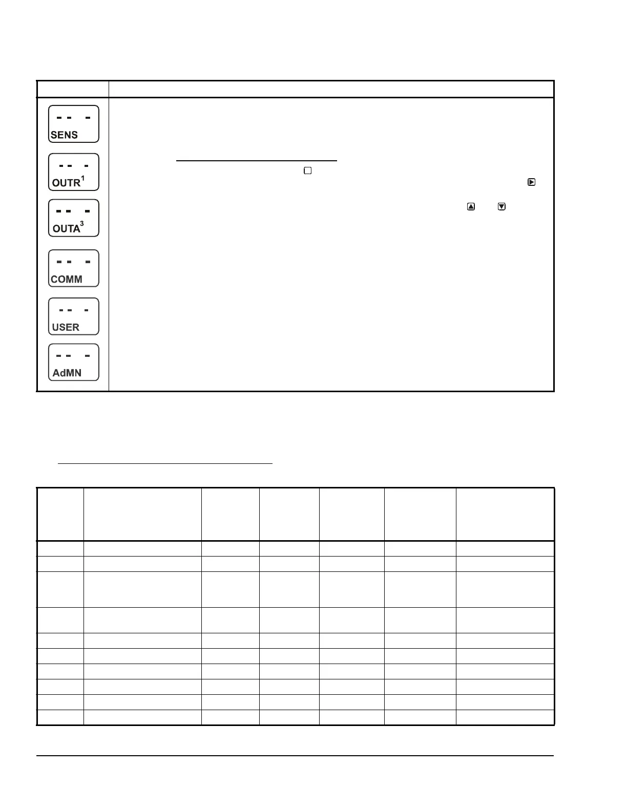
Setup Start Screens: Setup Start screens are view-only screens, from which you can access the setup
screens for the sensors or the displayed output; selections are not made in Setup Start screens. The
Sensor Setup Start screen is the first screen displayed when you access the System 450 setup screens.
Note: The numerical order and type of Output Setup Start screens are determined by the modules
selected for your System 450 control system and their physical order in the control system module
assembly. See Setting Up the Control System in the UI
on page 5 for more information.
From the Sensor Setup Start screen, press repeatedly to scroll through the Output Setup Start
screens for all of the outputs in your control system. When a Setup Start screen appears, press to
go to the setup screens for the sensors or the output displayed in the screen.
Note: In any Setup Start screen, you can return to the Main screens by pressing both
and
simultaneously. Also, the UI returns to the Main screen after 2 minutes of inactivity in any screen.
The screen examples show the Sensor, Relay Output 1, Analog Output 3, Communications, User
Password, and Administrator Password Setup Start screens.
Table 2: System 450 Startup Screen, Main Screens, Status Screens, and Setup Start Screens Information
and Procedures (Part 2 of 2)
LCD Screen Name, Description or Function, User Action, and Example
M
Table 3: System 450 Sensor Types, Setup Values, and Sensor or Transducer Product Codes (Part 1 of 2)
Sensor
Type
Unit of Measurement
Value
(Condition/Units)
Effective
Sensing
Range
Range of
Usable
Values
1
Resolution
Increment
Value
Minimum
Proportional
or Control
Band
Sensor Product
Type Number
2
F F (Temperature/degrees) -46 to 255 -40 to 250 1 1 A99B-xxx
C C (Temperature/degrees) -43 to 124 -40 to 121 0.5 0.5 A99B-xxx
rH % (Humidity/%RH) 1 to 100 10 to 95 1 2 HE-67Sx-xxxxx
HE-67Nx-xxxxx
HE-68Nx-0N00WS
P 0.25 INWC (Pressure/in. W.C.) -0.250 to
0.250
-0.225 to
0.250
0.005 0.01 DPT2650-R25B-AB
P 0.5 INWC (Pressure/in. W.C.) 0 to 0.5 0.025 to 0.5 0.005 0.01 DPT2650-0R5D-AB
P 2.5 INWC (Pressure/in. W.C.) 0 to 2.5 0.1 to 2.5 0.02 0.1 DPT2650-2R5D-AB
P 5 INWC (Pressure/in. W.C.) 0 to 5.0 0.25 to 5.0 0.05 0.25 DPT2650-005D-AB
P 8 bAR (Pressure/bar) -1 to 8 -1 to 8 0.05 0.1 P499Rxx-401C
P 10 INWC (Pressure/in. W.C.) 0 to 10 0.5 to 10 0.05 0.2 DPT2650-10D-AB
P 15 bAR (Pressure/bar) -1 to 15 -1 to 15 0.1 0.2 P499Rxx-402C

 Loading...


