System 450™ Series Control Module with Ethernet Communications Installation Instructions 9
Table 4 provides sensor setup information, procedures,
and example screens. Figure 6 on page 25 provides a
System 450 UI setup example.
P 30 bAR (Pressure/bar) 0 to 30 0 to 30 0.1 0.4 P499Rxx-404C
P 50 bAR (Pressure/bar) 0 to 50 0 to 50 0.2 0.4 P499Rxx-405C
P 100 PSI (Pressure/psi) 0 to 100 0 to 100 0.5 1 P499Rxxx101C
P 110
3
Hg/PSI (Pressure/Hg-psi) -10 to 100 -10 to 100 0.5 1 P499Rxxx100C
P 200 PSI (Pressure/psi) 0 to 200 0 to 200 1 1 P499Rxxx102C
P 500 PSI (Pressure/psi) 0 to 500 90 to 500 1 5 P499Rxx-105C
P 750 PSI (Pressure/psi) 0 to 750 150 to 750 2 6 P499Rxx-107C
HIF F (Temperature/degrees) -50 to 360
-40 to 350
4
1 1 TE-631x, TE-6000-x
TE-68NT-0N00S
HIC C (Temperature/degrees) -45.5 to
182
-40 to 176
4
0.5 0.5 TE-631x, TE-6000-x
TE-68NT-0N00S
bin
Open or Closed
5
(Dry Contacts)
N/A N/A N/A N/A N/A
1. Because of the way that the System 450 Differential Sensor (Sn-d) is set up and calculated with two identical sensors
(Sn-1 and Sn-2), the range of usable values is twice as large as a single sensor. Each Sensor Type has an equal number of
positive and negative values. See Table 9 for the range of usable values when an output references Sn-d.
2. Refer to the System 450 Series Modular Controls Product Bulletin (LIT-12011458), Catalog Page (LIT-1900549), or the
System 450 Series Controls Systems with Communications Technical Bulletin (LIT-12011826) for additional ordering
information for System 450 compatible sensors and transducers.
3. See Setting Up Outputs That Reference a P 110 Sensor
on page 10 for information on setting up System 450 outputs that
reference the P 110 Sensor Type.
4. Many of the temperature sensors that can be set up as HI°F or HI°C Sensor Types are not designed for use across the
entire range of usable values for HI°F and HI°C Sensor Types. Refer to the Technical Specifications for the sensor you
intend to use to determine the ambient temperature range that the sensor is specified to operate in. The TE-6000-6 Nickel
Sensor is the only sensor designed for use over the entire temperature range.
5. Selecting the bin Sensor Type for a sensor (Sn-1, Sn-2, or Sn-3) sets up the input to control relay outputs (only) based on
the state of the binary input contacts (open or closed) connected to the sensor input (Sn1, Sn2, or Sn3). See Binary Input
Control for Relay Outputs on page 11 for more information.
Table 3: System 450 Sensor Types, Setup Values, and Sensor or Transducer Product Codes (Part 2 of 2)
Sensor
Type
Unit of Measurement
Value
(Condition/Units)
Effective
Sensing
Range
Range of
Usable
Values
1
Resolution
Increment
Value
Minimum
Proportional
or Control
Band
Sensor Product
Type Number
2
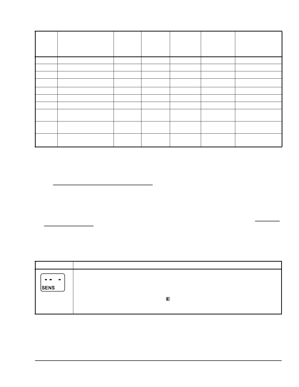
Table 4: System 450 Sensor Setup Screen Information and Procedures (Part 1 of 2)
LCD Screen Name, Description or Function, User Action, and Example
Sensor Setup Start Screen: The Sensor Setup Start screen is the first screen displayed when you
access the System 450 setup screens. From the Sensor Setup Start screen you can navigate to the
Output Setup Start screens or the Sensor Setup screens. See Figure 6.
Note: You must set up the input sensors before you can set up the control system outputs. The Sensor
Setup Start screen is view-only; selections are not made in Setup Start screens.
1. In the Sensor Setup Start screen, press
to go to the first Sensor Type Selection screen
(Sn-1) and begin setting up the sensors in your control system.
The screen example shows the Sensors Setup Start screen with flashing dashes.

 Loading...


