System 450™ Series Control Module with Ethernet Communications Installation Instructions 41
Network Configuration Page
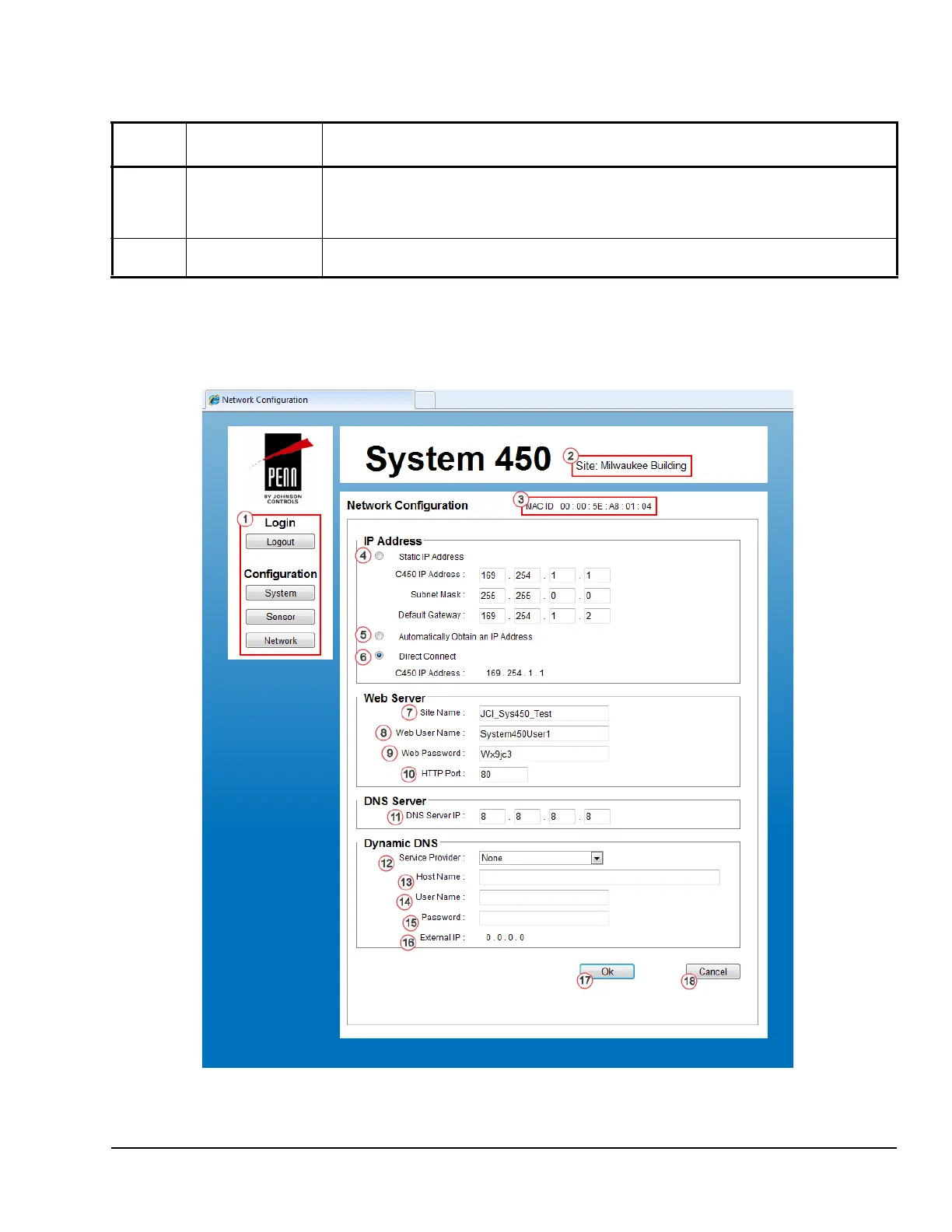
Figure 13 shows an example Network Configuration
Page for a System 450 control system that is set up
and operating.
Table 18 provides descriptions, user actions, and
references for the items called out in Figure 13.
14 Ok
Button
Click Ok to save any changes you made on this web page and go to the System
Configuration page.
Note: If you leave a web page before clicking Ok, any changes made on the page are not
saved, and the page reverts to the previous values.
15 Cancel
Button
Click Cancel to cancel any changes you made on this web page, revert to the previous
values on the web page, and go to the System Configuration page.
Table 17: System 450 Web UI Relay Output Configuration Page, User Actions, Descriptions, and
References (Part 3 of 3)
Callout
Number
Identifier / Item
Name
User Actions, Descriptions, References
Figure 13: System 450 Network Configuration Page Example

 Loading...


