System 450™ Series Control Module with Ethernet Communications Installation Instructions28
Note: You can monitor control system status and
configure the control system parameters in both the
local UI (LCD and four-button touch pad) and the web
UI. But you can only configure the control system’s
network settings in the web UI.
See Viewing Network Settings, Setting the Remote
Network UI Access Lock, and Resetting the Network
Settings on page 20 for the procedures on establishing
a direct connection between a computer and the
communications control module.
Refer to the System 450 Series Modular Control
Systems with Communications Control Modules
Technical Bulletin (LIT-12011826) for more detailed
information on connecting to your System 450
communications control system to a local network and
the Internet.
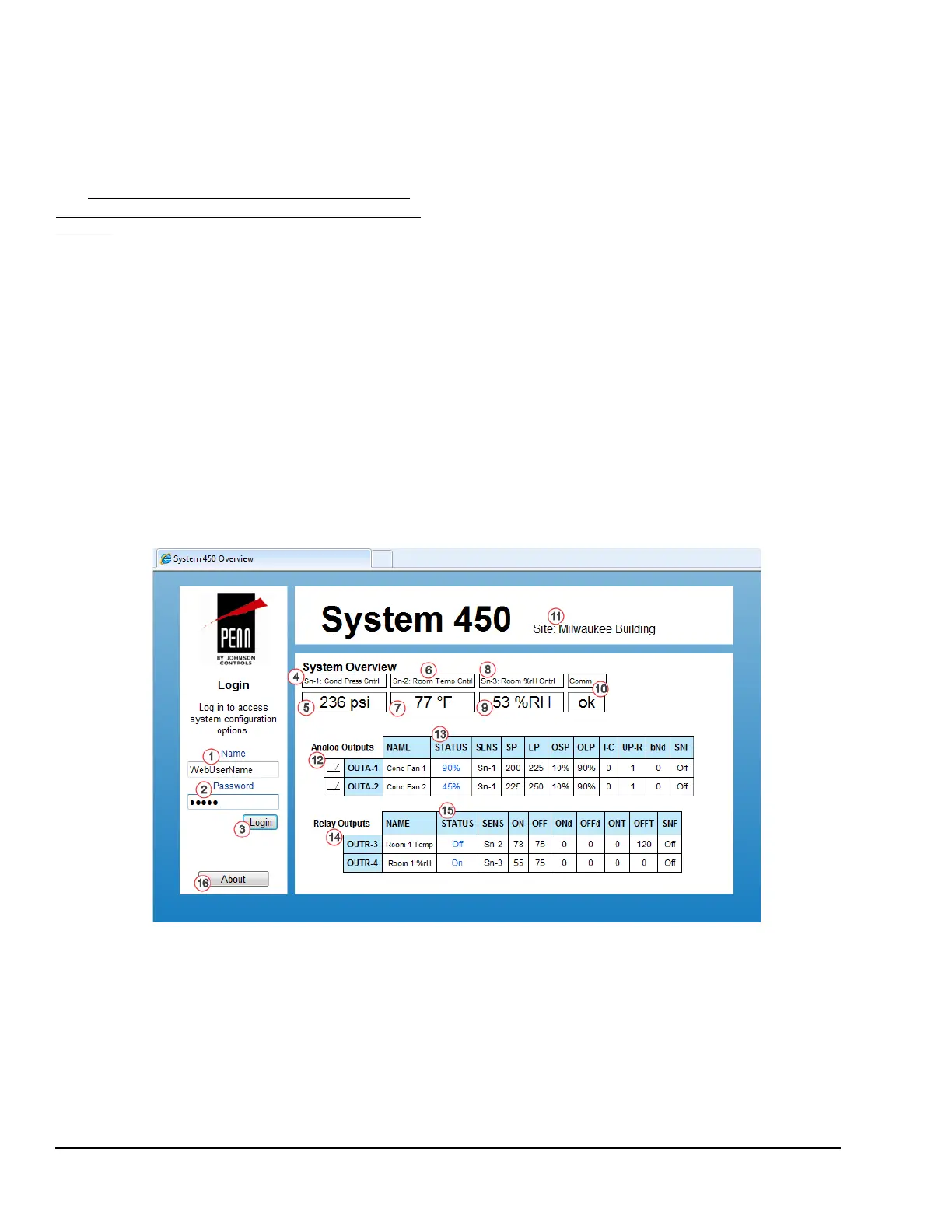
System Overview Page
Figure 8 shows an example System Overview page for
a System 450 control system that is set up and
operating. In the System Overview, you can view the
system status, system setup parameters, and values,
and you can log in to the control system’s web UI.
Note: You cannot make any changes to the system
configurations on the System Overview page. You must
log in to the web UI with the assigned user name and
password and then go to the sensor and output
configuration pages to change your control system
parameters and values.
This control system example uses the following input
sensors and outputs:
• a pressure sensor (Sn-1) to control the motor
speed of two condenser fans with analog outputs
(OUTA1 and OUTA2)
• a temperature sensor (Sn-2) to control the cooling
equipment (via Relay Output OUTR3) that
maintains room temperature
• a humidity sensor (Sn-3) to control the
humidification equipment (via Relay Output
OUTR4) to maintain the room humidity
Table 13 provides descriptions, user actions, and
references for the items called out in Figure 8.
Figure 8: System 450 System Overview Page Example

 Loading...


