System 450™ Series Control Module with Ethernet Communications Installation Instructions 17
Setting Up the Integration Constant, Update Rate,
and Output Deadband
The System 450 Integration Constant (I-C), the Update
Output Signal Rate (UP-R), and the Output Signal
Strength Deadband (bNd) are powerful tools for
controlling the analog outputs and your application’s
process loops.
Depending on your control system application, setting
up the I-C, UP-R, or bNd values to values other than
the factory-default values can significantly change the
behavior of an analog output. Refer to the System 450
Series Modular Control Systems with Communications
Control Modules Technical Bulletin (LIT-12011826) for
more information.
Table 9 provides information, procedures, guidelines,
and screen examples for setting up analog outputs on
System 450 control modules with communications.
See Figure 6 on page 25 for example menu flow of the
Analog Output 3 set up in Table 9.
IMPORTANT: If you set the I-C, UP-R, or bNd
values to values other than the default value, you
should operate and observe the affected analog
outputs and process loops through the entire range
of control. Failure to observe and adjust an analog
output set up to use the I-C, UP-R, or bNd features
can result in unexpected behavior and out of range
conditions in the affected process loops.
Table 9: System 450 Setup Screen Information and Procedures for Analog Output (Part 1 of 4)
LCD Screen Name, Description or Function, User Action, Example
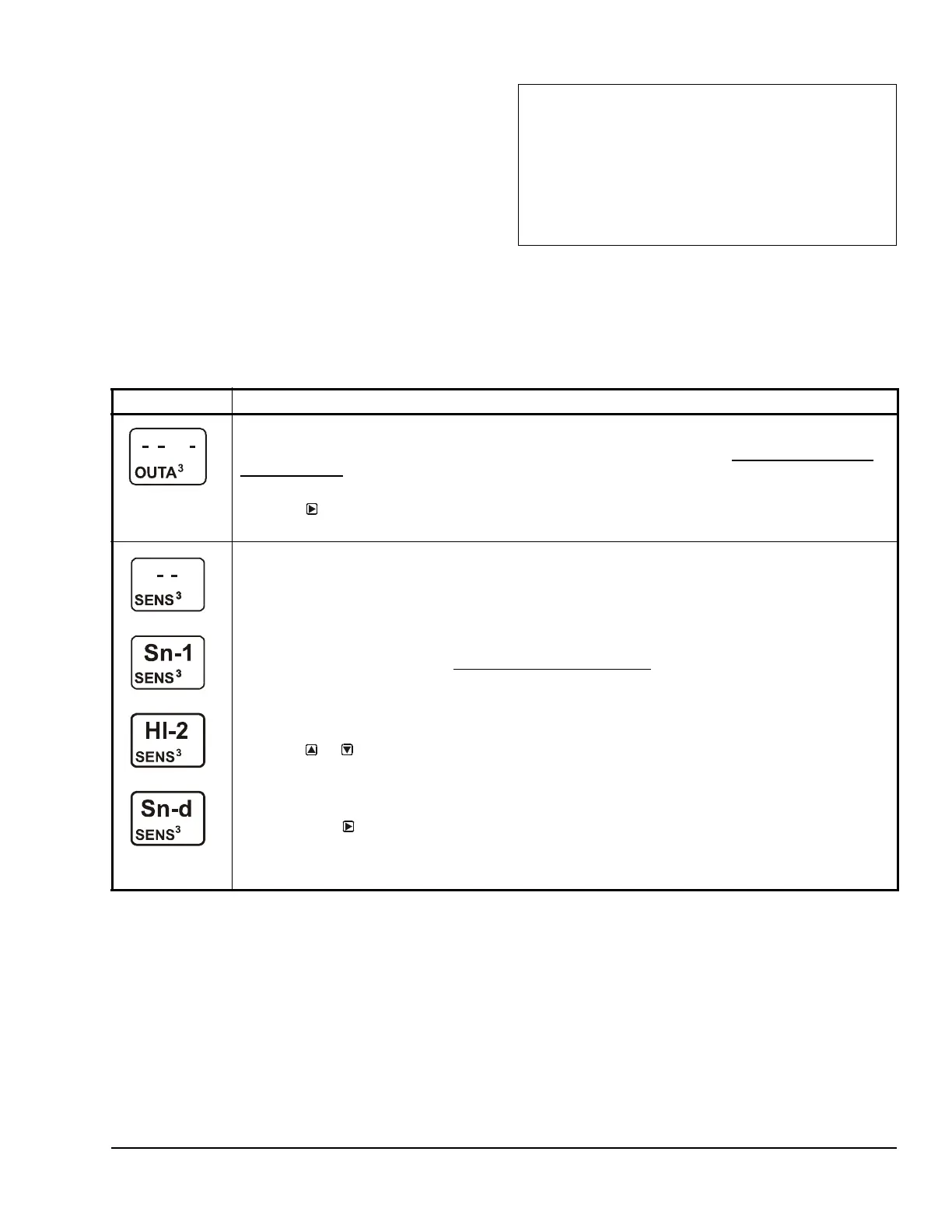
Analog Output Setup Start Screen: The output numbers and the output type (relay or analog) are
determined by the module types and configuration of your control system’s module assembly and are
automatically assigned when you connect power to the module assembly. (See Setting Up the Control
System in the UI on page 5.)
Note: You must set up the system’s sensors before you can set up the outputs.
1. Press
to go to this output’s Sensor Selection screen.
The screen example shows the Analog Output Setup Start screen for Output 3.
Sensor Selection Screen: The sensor you select here determines this output’s setup parameters and
values, including condition type, unit of measurement, minimum proportional band, default setup values,
and setup value ranges for several of the remaining output setup screens. If a sensor is not selected here,
this output’s remaining setup screens do not appear. If a sensor is already selected for this output, the
Sensor Selection screen does not appear here, and the Setpoint Selection (SP or dSP) screen appears
instead.
Note: You must select a sensor in this Sensor Selection screen and the selected sensor must be already
set up in the System 450 UI. (See Setting Up System 450 Sensors
.)
Note: On System 450 control modules with network communications, the functional sensors Sn-d and
HI-2 are available if Sn-1 and Sn-2 are the same Sensor Type. If Sn-1, Sn-2, and Sn-3 are the same
Sensor Type, the functional sensor HI-3 is also available. The Binary Input sensor is not available for
analog outputs.
2. Press or to select the sensor that this output references:
• For standard control action, select Sn-1, Sn-2, or Sn-3.
• For standard control action with High Input-Signal Selection, select HI-2 or HI-3.
• For differential control action, select Sn-d.
Then press
to save your sensor selection and go to the Setpoint Selection screen.
The top screen example shows the initial Sensor Selection screen for Analog Output 3 before a sensor is
selected. The remaining screen examples show some of the sensors that may be available for selection.
For the analog output example, Sn-1 is the selected Sensor for Output 3 as shown in the second screen.

 Loading...


