System 450™ Series Control Module with Ethernet Communications Installation Instructions16
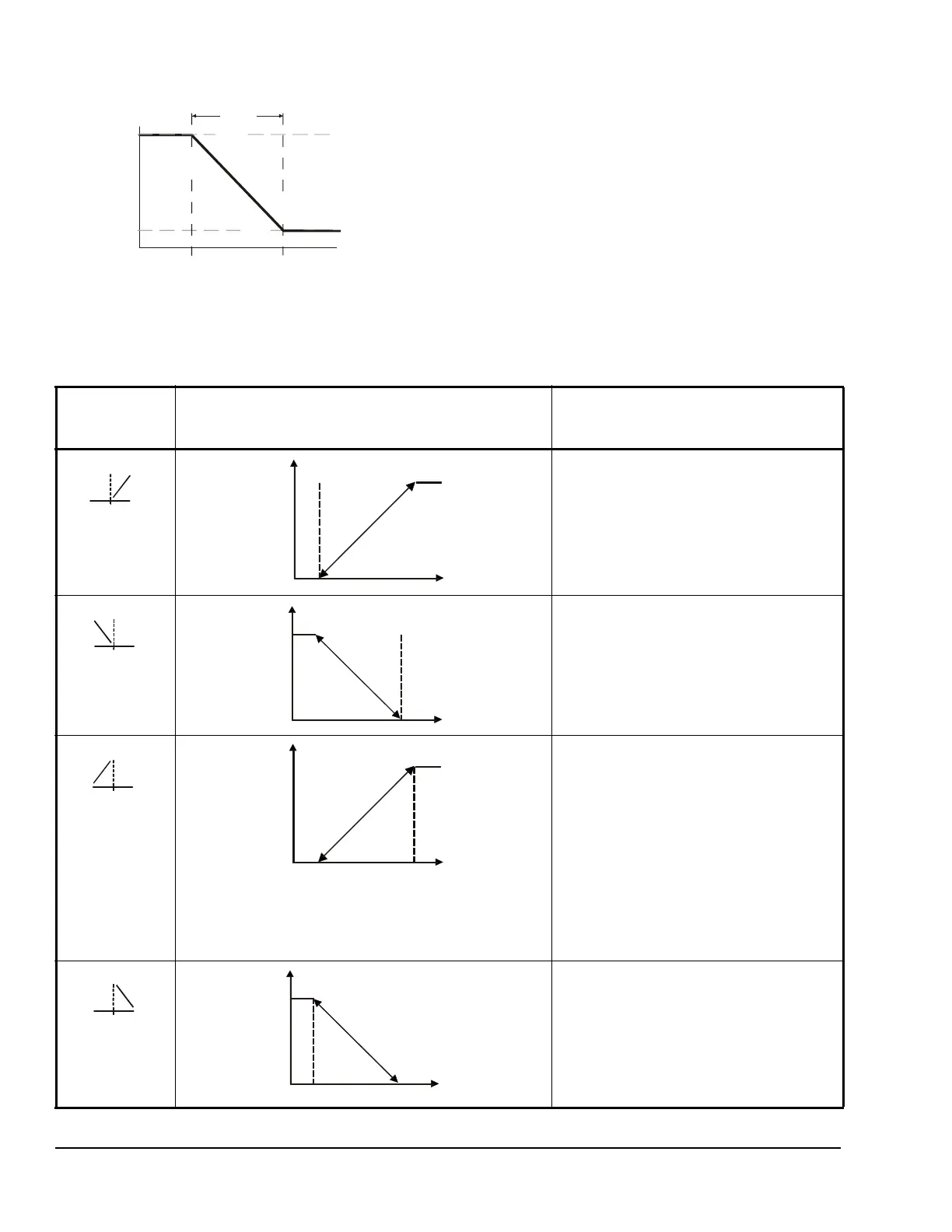
The control action between the input signal and the
output signal can be set up four ways, depending on
the values selected for the Setpoint (SP), End Point
(EP), Percent Output Signal Strength at Setpoint
(OSP), and Percent Output Signal Strength at End
Point (OEP). The LCD displays different Control Ramp
icons for the four control actions.
Table 8 shows the four Control Ramp icons and the
associated analog output setup value relationships.
Figure 5: Control Ramp Example for a Typical
Heating Application (SP > EP and OSP < OEP)
System Output
Condition Value
Less Greater
65°F
10%
70°F
SP > EP
SP = 70 ( )
EP = 65 ( )
OSP = 10 (%)
OEP = 100 (%)
OSP
SP
EP
Proportional
Band
Fig:sys450_cntrl_rmp_exmpl
Table 8: Analog Output Control Ramp Icons
Control Ramp
Displayed on
LCD
Control Action Set the Analog Output Value
Relationships for the Desired Control
Action and Control Ramp
SP < EP
OSP < OEP
SP > EP
OSP < OEP
SP > EP
OSP > OEP
SP < EP
OSP > OEP
Output Minimum at SP
a
l
SP=50°F EP=60°F
Output Minimum at SP
EP=50°F SP=60°F
Output Maximum at SP
EP=50°F SP=60°F
P
r
o
p
o
r
t
i
o
n
a
l
B
a
n
d
SP=50°F EP=60°F
OSP=100%
OEP=0%
P
r
o
p
o
r
t
i
o
n
a
l
B
a
n
d

 Loading...


