System 450™ Series Control Module with Ethernet Communications Installation Instructions 13
Sensor Selection Screen: The sensor you select here determines the output’s setup parameters and
values, including condition type, unit of measurement, minimum control band, default setup values, and
setup value ranges for several of the remaining output setup screens. If a sensor is not selected, the
remaining output setup screens do not appear. If a sensor is already selected for this output, the Sensor
Selection screen does not appear here and the Relay ON Selection (ON or dON) screen appears instead.
Note: You must select a sensor in this Sensor Selection screen and the selected sensor must be already
set up in the System 450 UI. (See Setting Up System 450 Sensors
.)
Note: On System 450 control modules with network communications, the functional sensors Sn-d and
HI-2 are available, if Sn-1 and Sn-2 are the same Sensor Type. If Sn-1, Sn-2, and Sn-3 are the same
Sensor Type, the functional sensor HI-3 is also available.
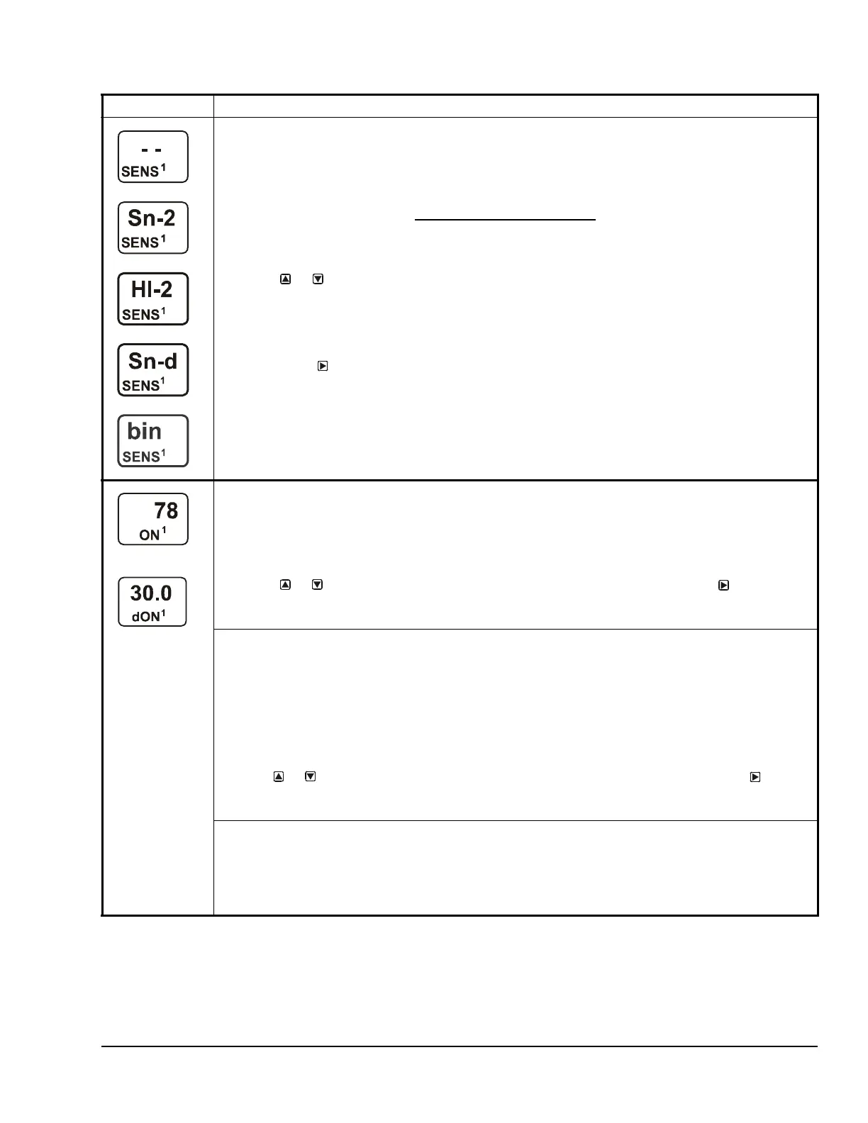
2. Press or to select the sensor that this output references:
• For standard control action, select Sn-1, Sn-2, or Sn-3.
• For standard control action with High Input-Signal Selection, select HI-2 or HI-3.
• For differential control action, select Sn-d.
• For binary input control of Relay Outputs, select bIn.
Then, press
to save your sensor selection and go to the Standard Relay ON Selection
screen or the Relay dON Selection.
The top screen example shows the initial Sensor Selection screen for Relay Output 1 before a sensor is
selected. The remaining screen examples show some of the sensors that may be available for selection.
For the Output Relay example, Sn-2 is selected as the Sensor for Output 1 as shown in the second
screen.
OR
When a Relay Output references Sn-1, Sn-2, Sn-3, HI-2, or HI-3, the Standard Relay ON Selection
screen appears.
Standard Relay ON Selection Screen: Select the value at which the relay turns on. Relay ON is defined
as relay LED On (lit), relay contacts N.O. to C are closed, and N.C. to C contacts are open.
Note: The value ranges and minimum control band are determined by the Sensor Type selected for the
sensor that the output references and are enforced in the Relay ON and Relay OFF Selection screens.
3. Press or to select the value at which the output relay turns on, then press
to save your
selection and go to Relay OFF Selection screen.
The screen example shows an ON value of 78 (°F) selected for Relay Output 1.
When a Relay Output References Sn-d, the Differential Relay dON Selection screen appears.
Differential Relay dON Selection Screen: Select the dON value at which the relay turns on. The dON
value is a differential value that represents the intended difference in the condition (temperature,
pressure, or humidity) between Sn-1 and Sn-2 (Sn-1 minus Sn-2) at which the relay is turned on.
Depending on the intended control action and the physical location of Sn-1 and Sn-2 sensors in the
condition process, dON may be a positive or negative value.
Note: The unit of measurement, resolution increment, minimum control band, and range of usable
values for dON and dOFF are determined by the Sensor Type selected for Sn-1 and Sn-2. (See Table 3
and Table 6 for more information.)
3. Press or to select the differential value at which the output relay turns on. Press to save
your selection and go to Relay dOFF Selection Screen.
The screen example shows a dON value of 30 (psi) selected for Relay Output 1.
When a Relay Output references a hard-wire sensor (Sn-1, Sn-2, or Sn-3) that is set up with the
bin (binary input) Sensor Type, the ON and OFF screens are not available. If you select and save a
sensor set up as a binary input in Step 2, the ON Delay (ONd) screen appears. Go to Step 5.
Binary Input Control: Relay outputs that reference a sensor set up with the bin Sensor Type are
controlled by the binary input contacts state (open or closed). The ON and OFF values are not used to
control relay outputs that reference a binary input sensor.
Table 7: System 450 Setup Screen Information and Procedures for Relay Outputs (Part 2 of 4)
LCD Screen Name, Description or Function, User Action, Example

 Loading...


