JOHNSON CONTROLS
25
SECTION 2 - INSTALLATION
FORM 160.75-N1
ISSUE DATE: 4/30/2014
2
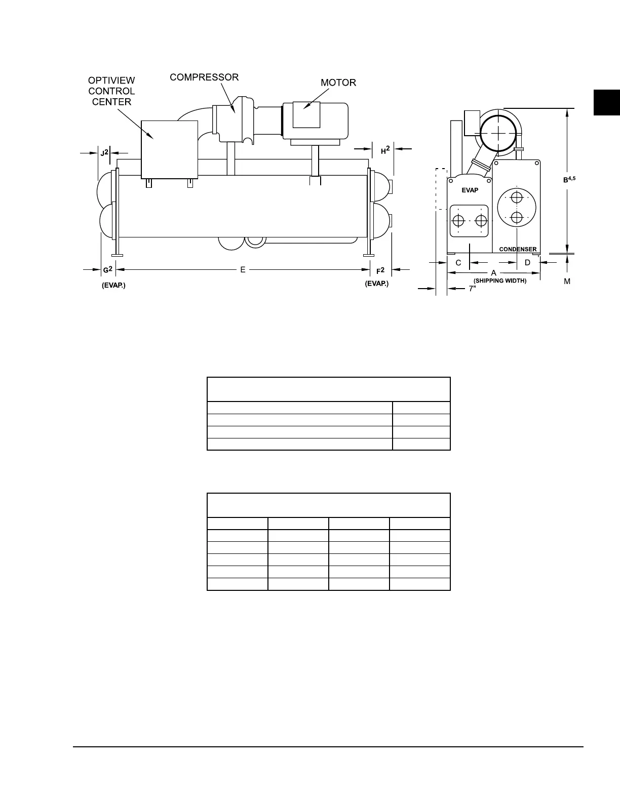
NOTES:
1. All dimensions are approximate.
2. For compact waterboxes (shown above), determine overall unit length by adding waterbox depth to tube sheet length.
3. Water nozzles can be located on either end of unit. Add 1/2" (13 mm) to nozzle length for anges connections.
4. To determine overall height, add 7/8" (22 mm) for isolators.
5. Use of motors with motor hoods may increase overall unit dimensions.
FIGURE 13 - DIMENSIONS – H COMPRESSOR UNITS (FT–IN)
H COMPRESSOR UNITS (STANDARD)
ADDITIONAL OPERATING HEIGHT
CLEARANCE TO FLOOR
Type of Chiller Mounting M
Neoprene Pad Isolators 1 3/4"
Spring Isolators 1" Deflection 1"
Direct Mount 3/4"
H9 COMPRESSORS
EVAPORATOR – CONDENSER SHELL CODES
I-K & K–K K–O M–M
A 7'-6 1/2" 8'-9 1/4" 8'-7"
B 10'-4" 10'-7 5/8" 10'-10 1/2"
C 2'-1 1/4" 2'-1 1/4" 2'-4 1/2"
D 1'-8" 2'-3 3/8" 1'-11"
E 14'-0" 14'-0" 14'-0"
LD07135

 Loading...