JOHNSON CONTROLS
37
SECTION 2 - INSTALLATION
FORM 160.75-N1
ISSUE DATE: 4/30/2014
2
NOTES:
1. All dimensions are approximate.
2. Standard water nozzles are Schedule 40 pipe size, furnished as welding stub-outs with grooves, allowing the option of welding, anges,
or use of Victaulic couplings. Factory-installed, class 150 (ANSI B16.5, round slip-on, forged carbon steel with 1/16" raised face), water
anged nozzles are optional (add 1/2" to nozzle length). Companion anges, nuts, bolts, and gaskets are not furnished.
3. One-, two-, and three-pass nozzle arrangements are available only in pairs shown and for all shell codes. Any pair of evaporator nozzles
may be used in combination with any pair of condenser nozzles. Compact waterboxes on one heat exchanger may be used with Marine
Waterboxes on the other heat exchanger.
4. Condenser water must enter the waterbox through the bottom connection for proper operation of the sub-cooler to achieve rated performance.
5. Add dimension "M" as shown on pages per unit dimensions page for the appropriate isolator type.
6. Heat recovery units offer marine waterbox option for tower (lower) bundle only.
CONDENSER
SHELL CODE
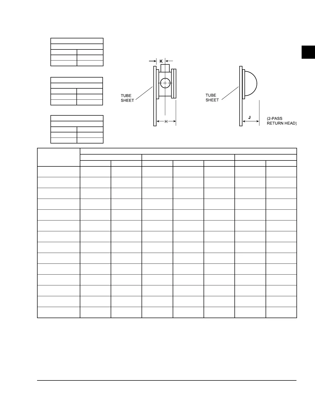
CONDENSER NOZZLE DIMENSIONS FT-IN (MM)
1-PASS 2-PASS 3-PASS
H K H J K H K
A
1'-9"
(533)
0'-9 7/8"
(251)
1'-4 3/4"
(425)
0'-6"
(152)
0'-7 3/4"
(197)
1'-4 3/4"
(425)
0'-7 3/4"
(197)
B
6
1'-10 1/2"
(572)
0'-10 1/2"
(267)
1'-8"
(508)
0'-10 1/2"
(267)
0'-9 1/4"
(235)
1'-8"
(508)
0'-9 1/4"
(235)
C,D
2'-0"
(610)
0'-11 1/8"
(283)
1'-7 1/2"
(495)
0'-6 3/8"
(162)
0'-9"
(229)
1'-7 1/2"
(495)
0'-9"
(229)
E,F
2'-0 1/2"
(622)
0'-11 1/2"
(292)
1'-10 1/4"
(565)
0'-7"
(178)
0'-9 7/8"
(251)
1'-10 1/4"
(565)
0'-9 7/8"
(251)
I
6
2'-3"
(686)
1'-0 3/4"
(324)
1'-10 1/2"
(572)
0'-11 1/2"
(292)
0'-10 1/2"
(267)
1'-10 1/2"
(572)
0'-10 1/2"
(267)
J,K,L
2'-8 3/8"
(822)
1'-3 3/8"
(391)
2'-8 3/8"
(822)
0'-7 1/2"
(191)
1'-3 3/8"
(391)
2'-8 3/8"
(822)
1'-3 3/8"
(391)
M,N
2'-11"
(889)
1'-4"
(406)
2'-11"
(889)
1'-0"
(305)
1'-4"
(406)
2'-11"
(889)
1'-4"
(406)
O
6
2'-6 1/4"
(768)
1'-2 1/4"
(362)
2'-1 3/4"
(654)
1'-1 1/2"
(343)
1'-0"
(305)
2'-1 3/4"
(654)
1'-0"
(305)
P, Q
2'-8"
(813)
1'-2 1/2"
(368)
2'-4"
(711)
0'-9 1/2"
(241)
1'-0 1/2"
(318)
2'-4"
(711)
1'-0 1/2"
(318)
R,S
2'-8"
(813)
1'-2 1/2"
(368)
2'-6"
(762)
1'-0"
(305)
1'-1 1/2"
(343)
2'-6"
(762)
1'-1 1/2"
(343)
T,V,W
3'-0"
(914)
1'-4 1/2"
(419)
2'-6"
(762)
0'-11"
(279)
1'-1 1/2"
(343)
2'-6"
(762)
1'-1 1/2"
(343)
U
6
2'-8"
(813)
1'-3"
(381)
2'-4"
(711)
1'-2 1/4"
(362)
1'-1"
(330)
2'-4"
(711)
1'-1"
(330)
X,Z
3'-5 1/2"
(1,054)
1'-6 1/2"
(470)
3'-0 1/2"
(927)
1'-2"
(356)
1'-4 1/4"
(413)
2'-9 1/2"
(851)
1'-2"
(356)
Y
6
3'-4 3/4"
(1,035)
1'-7 1/4"
(489
3'-0 1/4"
(921)
1'-8 3/4"
(527)
1'-5"
(432)
3'-0 1/4"
(921)
1'-5"
(432)
CONDENSER
1-PASS
IN OUT
11 16
16 11
CONDENSER
2-PASS
IN OUT
12 13
17 18
CONDENSER
3-PASS
IN OUT
15 20
19 14
CONDENSER – NOZZLE ARRANGEMENTS – STANDARD - FT - IN (MM)
FIGURE 25 - DIMENSIONS – CONDENSER NOZZLE ARRANGEMENTS - STANDARD (MM)
LD07177

 Loading...