FORM 160.75-O1 (211)
JOHNSON CONTROLS
6
LIST OF FIGURES
LIST OF TABLES
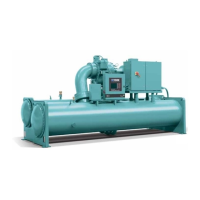
FIGURE 1 - Model YK Chiller .................................................................................................................................... 7
FIGURE 2 - Compressor Prerotation Vanes ..............................................................................................................8
FIGURE 3 - Refrigerant Flow-Thru Chiller (Falling Film Evaporator) ........................................................................9
FIGURE 4 - Refrigerant Flow-Thru Chiller (Flooded Evaporator)............................................................................10
FIGURE 5 - Oil Level Indicator ............................................................................................................................... 11
FIGURE 6 - Chiller Starting Sequence And Shutdown Sequence (Em Starter And Solid State Starter) ................ 12
FIGURE 7 - Chiller Starting Sequence And Shutdown Sequence (Variable Speed Drive) .....................................12
FIGURE 8 - Liquid Chiller Log Sheets .....................................................................................................................14
FIGURE 9 - System Components Front View .........................................................................................................18
FIGURE 10 - System Components Rear View ........................................................................................................ 19
FIGURE 11 - Schematic Drawing – (YK) Compressor Lubrication System............................................................. 20
FIGURE 12 - Oil Return System..............................................................................................................................23
FIGURE 13 - Charging Oil Reservoir With Oil .........................................................................................................24
FIGURE 14 - Evacuation Of Chiller ......................................................................................................................... 27
FIGURE 15 - Saturation Curve ................................................................................................................................29
FIGURE 16 - Diagram, Megging Motor Windings ...................................................................................................30
FIGURE 17 - Motor Starter Temperature And Insulation Resistances ....................................................................31
Megging The Motor .........................................................................................................................................30
Compressor .................................................................................................................................................... 33
Electrical Controls ..........................................................................................................................................34
SECTION 7 - PREVENTIVE MAINTENANCE ........................................................................................................ 35
Compressor .................................................................................................................................................... 35
Compressor Motor ..........................................................................................................................................35
Greased Bearings .........................................................................................................................................35
Leak Testing ...................................................................................................................................................36
Evaporator And Condenser ............................................................................................................................36
Oil Return System ..........................................................................................................................................36
Electrical Controls ..........................................................................................................................................36
TABLE OF CONTENTS (CONT'D)
TABLE 1 - Operation Analysis Chart .......................................................................................................................25
TABLE 2 - System Pressures .................................................................................................................................28
TABLE 3 - Bearing Lubrication ................................................................................................................................35

 Loading...


