Page Issue 01Chapter - Hydraulic System8:2
VT551 - Maintenance
GENERAL DESCRIPTION
The hydraulic system may be divided into four hydraulic circuits fed from a common hydraulic reservoir.
1 Sweep system.
2 Water system.
3 Fan drive system and load discharge.
Hydraulic filtration is provided by suction filters within the hydraulic tank, together with replaceable type ‘in
line’ return filter mounted externally on the upper face of the hydraulic tank.
CIRCUIT PRESSURES
Test points are provided on the hydraulic system to carry out pressure checks.
POINT NO. FUNCTION
T7 Sweep system test point
T8 Fan drive system/body discharge
T9 Water system (i.e. Supawash)
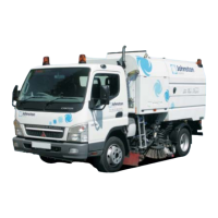
To set the hydraulic pressures select menu 4. Set
pressures from the main CANview screen and choose
sub menu 11.
NB : There is a default setting on this menu 4.11.6
to input default figures, in order for you to be able to
initially set the machine up and run the engine.
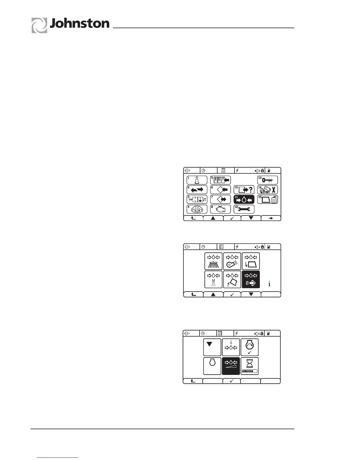
BRUSH PRESSURE - MENU 4.11.1
Connect a suitable 250 bar gauge to test point T7 (see
Valve Identification).
It is necessary to remove hose 201 in port C1 of the
‘sweep block 4’ and plug with a suitable plug and
also cap off the hose. Follow the on screen CANview
instructions.
This pressure should be 225 bar.
If necessary manually adjust RV1.
NB : DO NOT run the pressure test for longer than 30 seconds or damage maybe caused to the system.
93OG. 027-35