Page Issue 01Chapter - Remove and Refit Procedures13:2
VT551 - Maintenance
This section describes the removal and refitting of some of the major components on the machine. These
are not routine jobs and should normally only need to be undertaken when overhauling or exchanging
these units.
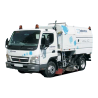
1. WATER PUMP - REMOVAL AND REFITTING
1. Isolate the water supply at the filter unit.
2. Mark up the position of the water and hydraulic feed
and return pipes before disconnecting. It will be
necessary to cap the hydraulic pipes to prevent oil loss.
3. Remove the 4 bolts (A) holding the pump brackets to
the centre subframe crossmember.
4. Refit in the reverse order.
5. Turn on the water at the filter and run pump to check for
water and hydraulic leaks.
NB - It is possible to replace the pump suction and discharge
valves in situ.
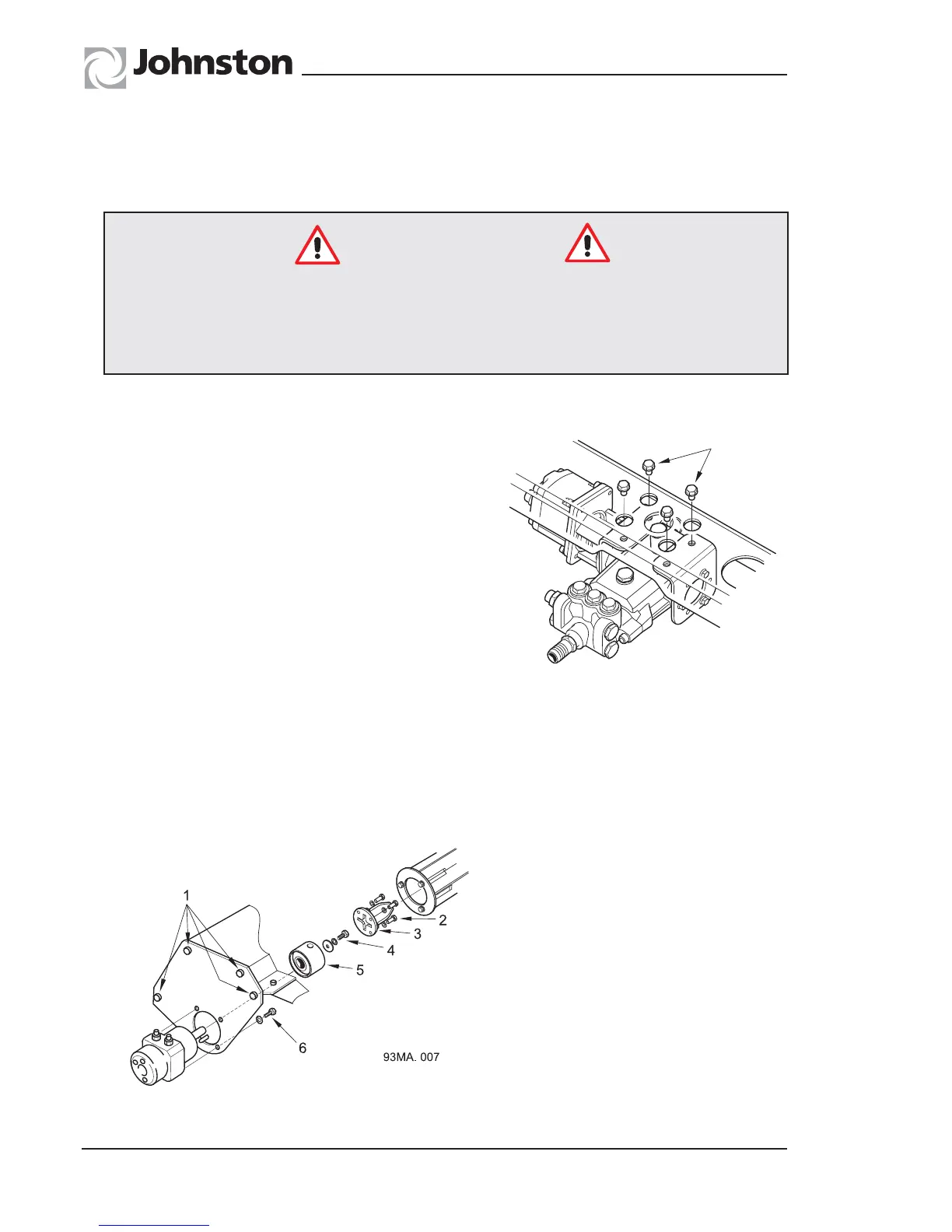
2. WIDE SWEEP BRUSH MOTOR - REMOVAL AND REFITTING
1. Remove the brush stock as described in Chapter 6.
2. Unscrew the four end plate securing setscrews and remove plate complete with motor assembly and
drive shaft or drive dog.
FIGURE 4 - WIDE SWEEP BRUSH
MOTOR
1. End plate securing screws.
2. Drive shaft retaining screws.
3. Drive shaft/drive dog.
4. Retaining plate.
5. Drive adaptor retaining screw.
6. Drive adaptor
7. Motor securing screws
The hinged prop stowed beneath the body SHOULD BE USED AT ALL TIMES to prop the body
when carrying out any inspection, servicing or maintenance work beneath the body.
Disconnect or isolate the battery before undertaking any of the following operations
on the sweeper and remove the chassis ignition key to isolate the power units.
Safety Precautions
93MA.018
A