Page Issue 01Chapter - Pneumatic System11:6
VT551 - Maintenance
WIDE SWEEP BRUSH REGULATOR MAINTENANCE
Before any work can be carried out on these units, they must be removed from their locations under the
ends of the subframe crossmember+ as follows.
Exhaust the system using filter regulator shut off valve, disconnect pipes from regulator and shuttle
valve, unscrew regulator securing nut. The regulator, shuttle and non-return valves can be removed as
a complete assembly.
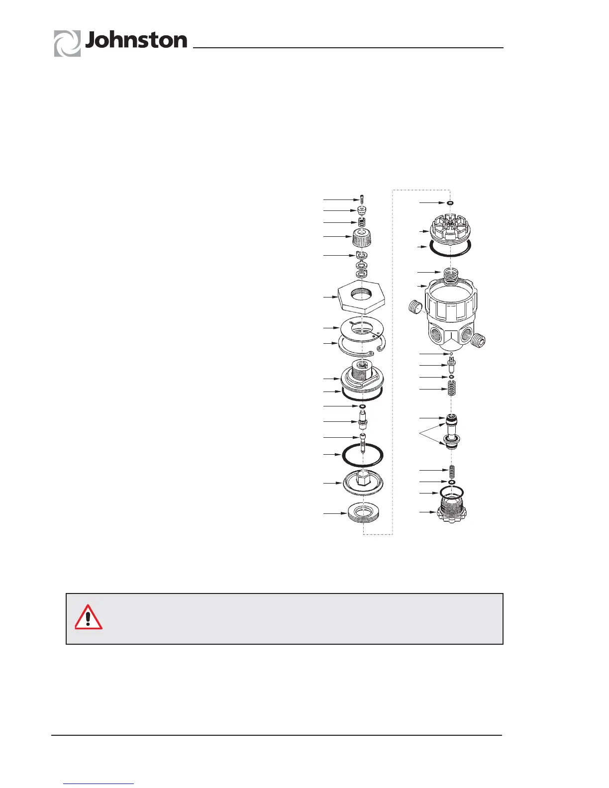
REGULATOR
Remove the regulator by undoing the securing nut
(A). Use retaining ring pliers to remove the top plate
(6) and retaining ring (7). Pull cap (8) and ‘O’ ring (9)
from body.
Unscrew socket head screw (1), then remove button
(2), spring (3), knob (4), tumblers (5), couple (10) and
‘O’ ring (11).
Remove, as an assembled unit, the adjusting screw
(12) with upper and lower piston assemblies (Items 13
through 20). Remove spring (21).
Unscew the adjusting screw (12), then separate upper
and lower piston assemblies (Item 13 through 20).
The adjusting screw has left hand threads. Make sure
‘O’ ring (19) remains attached to the lower piston. If
not, retrieve it from inside the upper piston (13).
Unscrew bottom plug (22) to gain access to the parts
(23 through 36) located in the lower portion of the
body.
Clean and inspect each item for damage.
A repair kit, Part No. 253-10, is available comprising
Items 9, 11, 12, 14, 19, 20, 23-27, 29, 30 and 36.
When reassembling, lightly smear the ‘O’ rings and
rubbers with a silicon grease. Reassemble in the
reverse procedure.
PC. 0014
1
19
18
20
21
37
25
26
27
28
29
36
23
24
22
30
2
3
4
5
A
6
7
8
9
11
10
12
14
13
15
Make sure retaining ring (7) is fully seated in the groove in the body before
testing or refitting onto the machine.